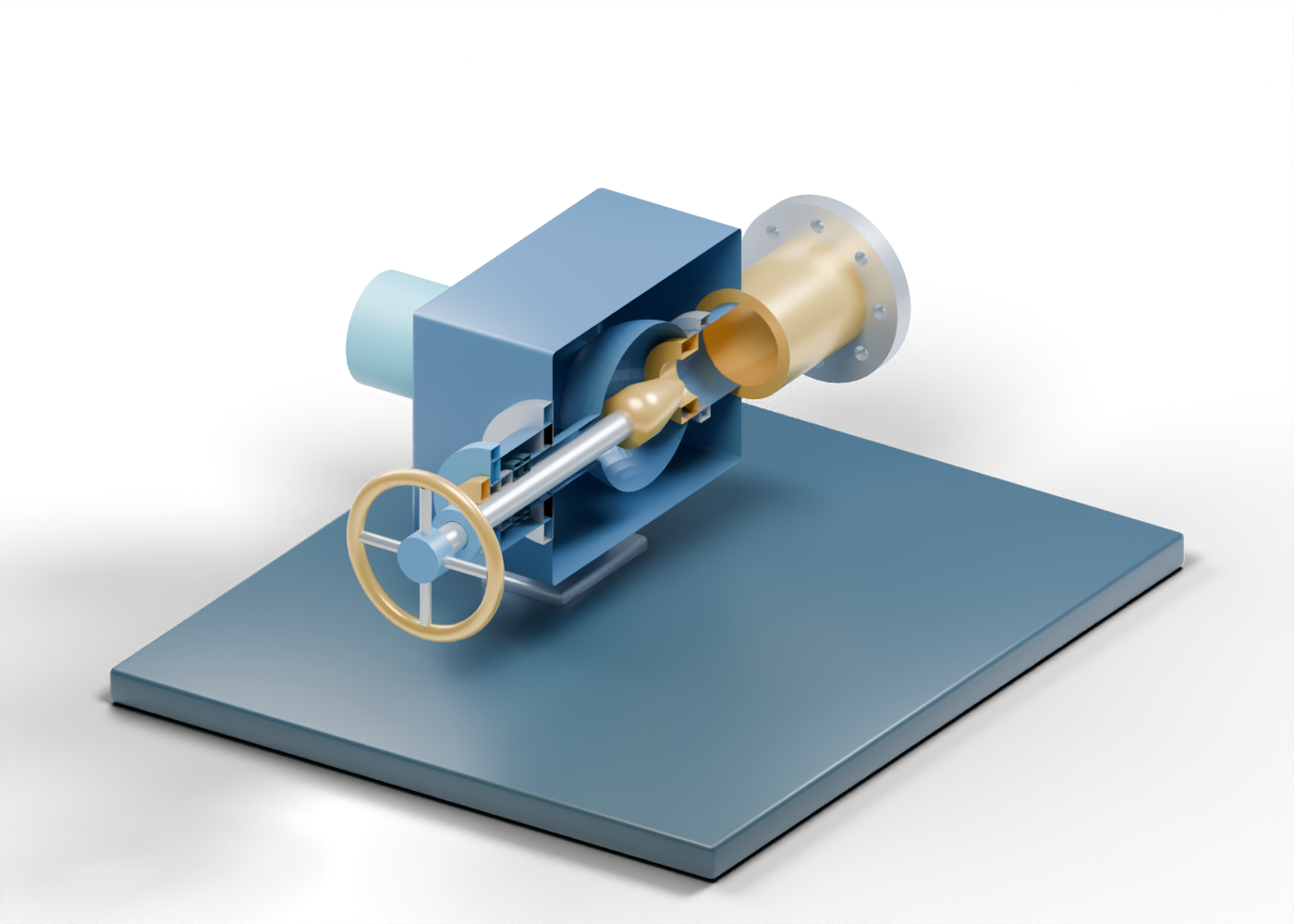
1. Where a production choke fits
An adjustable choke used for well completions can sit on or near a production tree. Changing its opening influences the rate and pressure of production fluids moving toward a pipeline or process facility. The same glossary also defines a drilling well-control choke; the two applications should not be conflated. Start with our separate production-tree lesson, then open the original choke explorer. These models are independent illustrations, not a selected well assembly.
2. Find the open boundaries
The blue inlet neck meets one of three actual openings in the complete body wall. A central chamber connects the illustrated inlet, outlet and stem-side regions. The outlet neck is a different boundary, beyond the restriction region. The open geometry helps identify parts. It does not prove a pressure-containing connection, a flow route under operating conditions or a rated body.
3. Separate the needle from its seat
SLB describes needle-and-seat choke technology and distinguishes adjustable from positive trim. In our invented cutaway, the annular seat has an actual opening, while the solid tapered needle points toward it from the chamber. A retainer marker is another separately selectable role. The taper stops short of the seat. That visible gap is a static teaching pose, not a calibrated setting, seal, flow coefficient or pressure-drop result.
A real choke's restriction, trim material and control arrangement depend on the selected equipment and service. Sand, gas and liquid behaviour cannot be inferred from the colours or the gap in this model.
4. Read the adjustment and containment questions
The stem extends from the needle toward an open bonnet-region sleeve. Two packing-location rings and a follower show where stem sealing would need to be considered. A manual-wheel cue makes this one illustrative configuration recognizable. The wheel is static: the model has no thread engagement, moving stem, tested packing, control system or instruction for opening a real well.
| What you can inspect in this original model | What requires real equipment evidence |
|---|---|
| Three body passages and two open necks | Selected connections and pressure integrity |
| Separate annular seat and tapered needle | Trim geometry, erosion and flow characteristic |
| Visible needle-to-seat gap | Actual position, leakage and pressure drop |
| Stem, bonnet and packing locations | Joint design, seal performance and actuation |
| Bored outlet flange marker | Rated facing, fastening and downstream piping |
5. Connect the next production questions
Some wellstreams carry solids that must be considered before downstream equipment. Our independent wellhead sand-separator lesson lets you ask where such handling could occur; it does not mean every well has that exact equipment or that the two drawings are connected. The oil-battery treatment scene shows later separation, storage and transfer roles at invented scales. Neither scene establishes a process design, product specification or operating sequence for the choke shown here.
6. Use the model to ask better questions
Use the 44-part choke explorer to identify the inlet, seat, needle, stem and outlet. For a real production decision, ask which selected choke and trim are installed, what drawings and test records apply, how pressures and rates are measured, what erosion/solids evidence exists, and which qualified procedures govern that well. A public 3D lesson can organize vocabulary and questions; it cannot replace those records or qualified review.