Gas compression
Inside a multistage centrifugal gas compressor
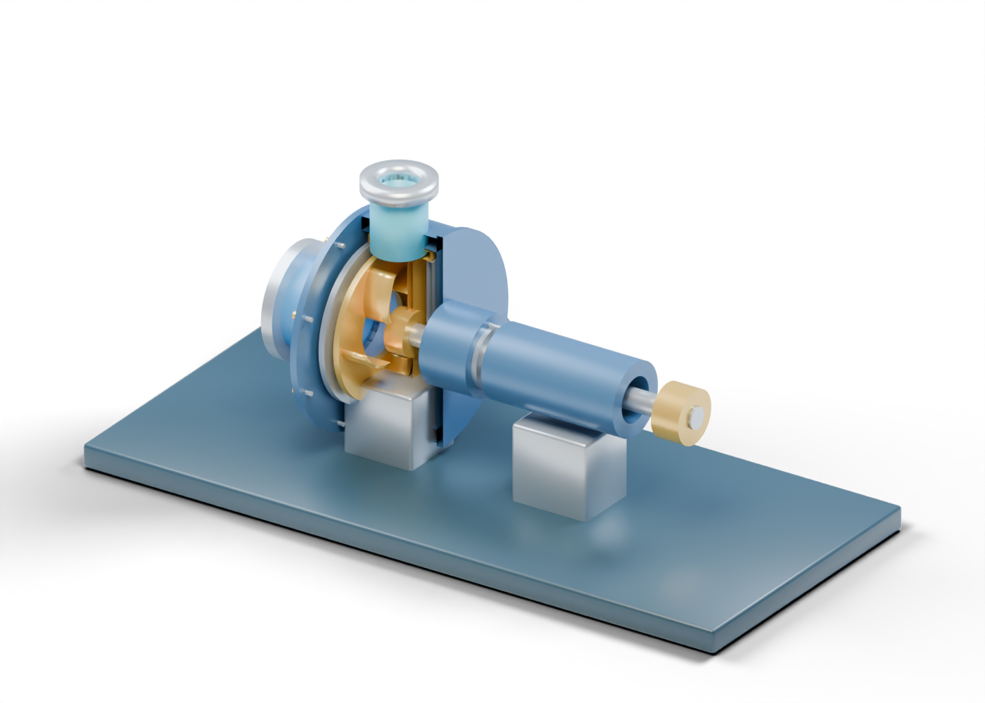
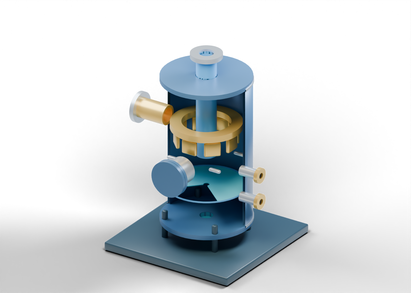
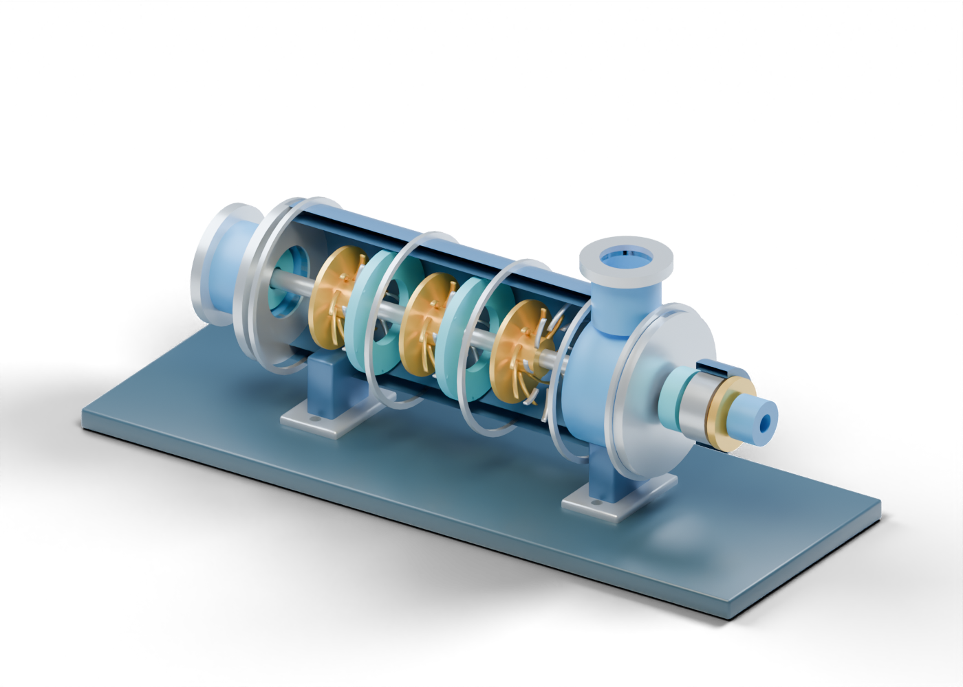
Explore an original 121-part compressor cutaway and distinguish impellers, diffusers, return guides, suction and discharge boundaries, seals and bearings.
Read the illustrated guideTHE CONTEXT BEHIND THE HEADLINES
Go inside the equipment, follow the process and learn to read the record. Original illustrated guides connect Canadian energy news to the components and concepts behind it.
Reporting here. Deep equipment learning at AlbertaOil.
OilNews guides help readers interpret energy stories and market records. Our equipment guides are readable companions to AlbertaOil’s original interactive Atlas, which is the home of detailed model and component education. Shared original illustrations connect the two; they are not separate equipment designs.
66
Original equipment & market guides
35
Topics across the industry
Two distinct roles
OilNews explains the news. AlbertaOil owns the deep interactive equipment lesson.
Showing 66 of 66 guides.
Gas compression
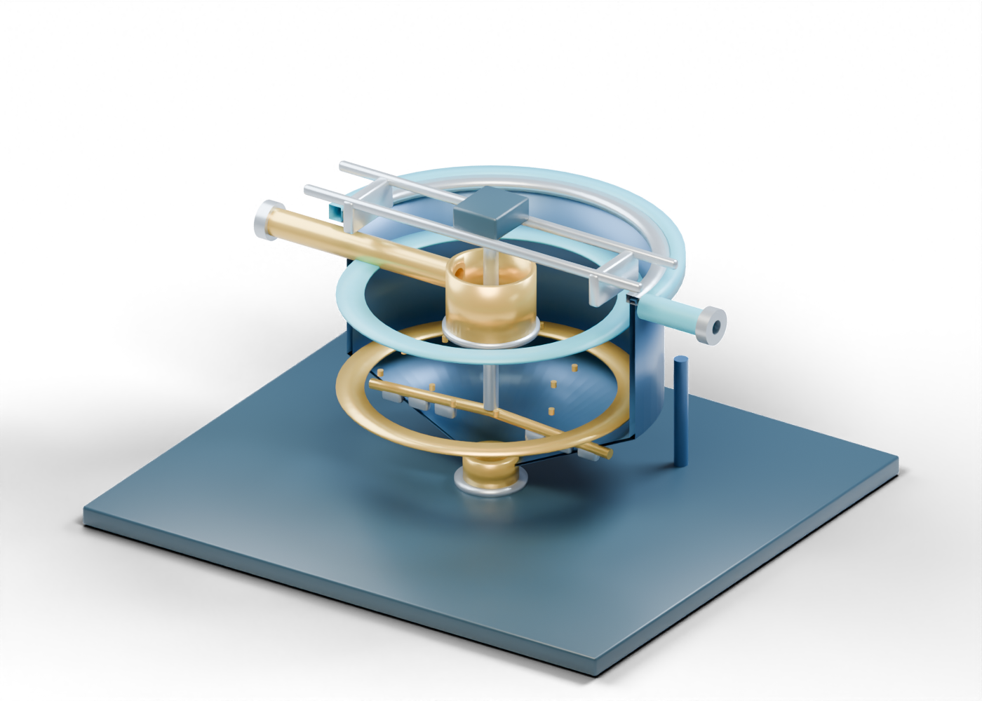
Explore an original 121-part compressor cutaway and distinguish impellers, diffusers, return guides, suction and discharge boundaries, seals and bearings.
Read the illustrated guideWell production
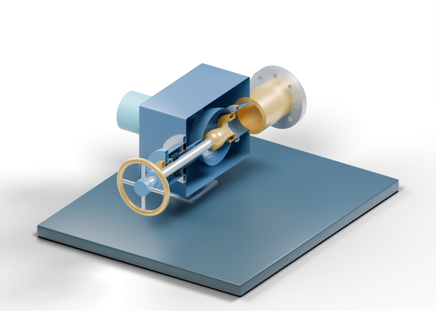
Follow an original 44-part choke cutaway from the production-tree side to the open outlet, and separate visible parts from pressure and flow claims.
Read the illustrated guidePumps and rotating equipment
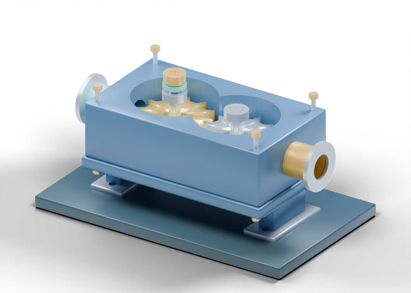
Explore an original 38-part gear-pump cutaway and learn what its two gears, open housing, ports and shaft regions can—and cannot—tell you.
Read the illustrated guidePumps and rotating equipment
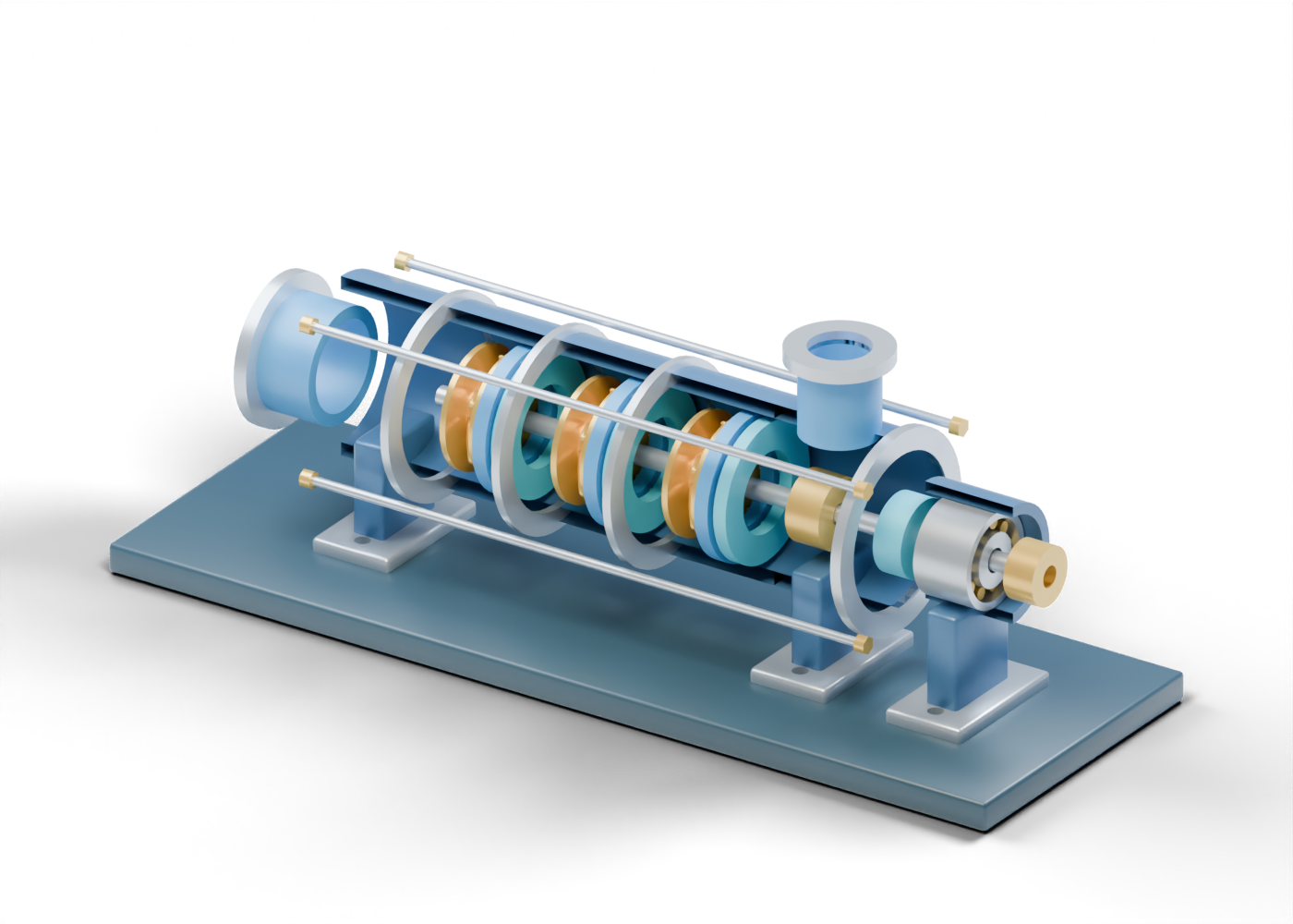
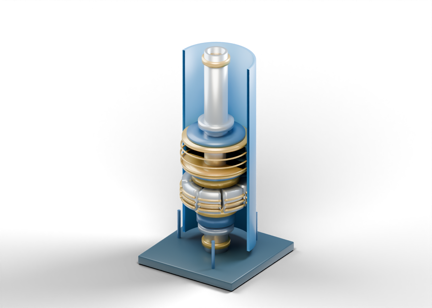
Follow an original 115-part pump cutaway through three impeller, diffuser and return-guide stages, then distinguish visible components from measured performance.
Read the illustrated guideDrilling
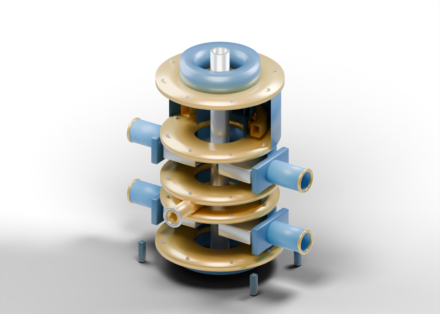
Explore an original 87-part 3D cutaway of a generic surface blowout-preventer stack, including actual open passages and the critical distinction between notched and flat retracted rams.
Read the illustrated guideDrilling
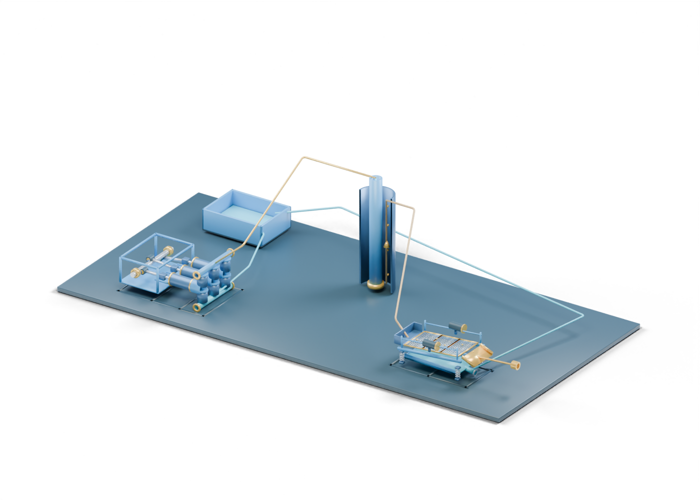
Follow an original 212-part 3D map through a mud pump, open drillstring and annulus, shale shaker and distinct surface exits—then see what a real circulation claim must prove.
Read the illustrated guideDrilling
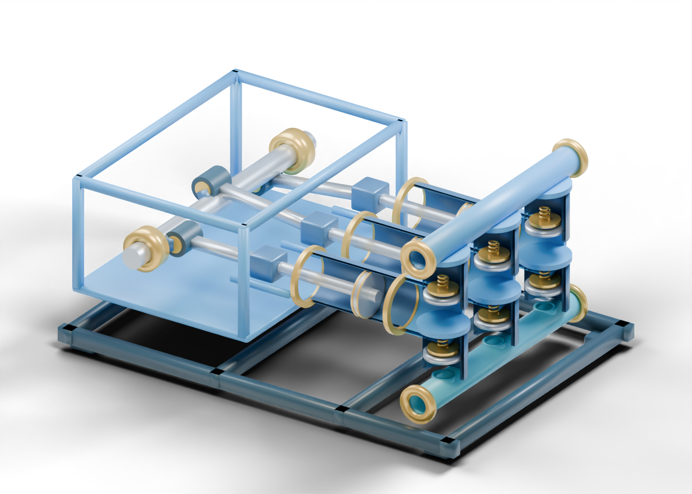
Explore an original 112-part three-bank cutaway and learn what its open liners, valve seats and manifolds can—and cannot—tell you about drilling-fluid pumping.
Read the illustrated guideDrilling
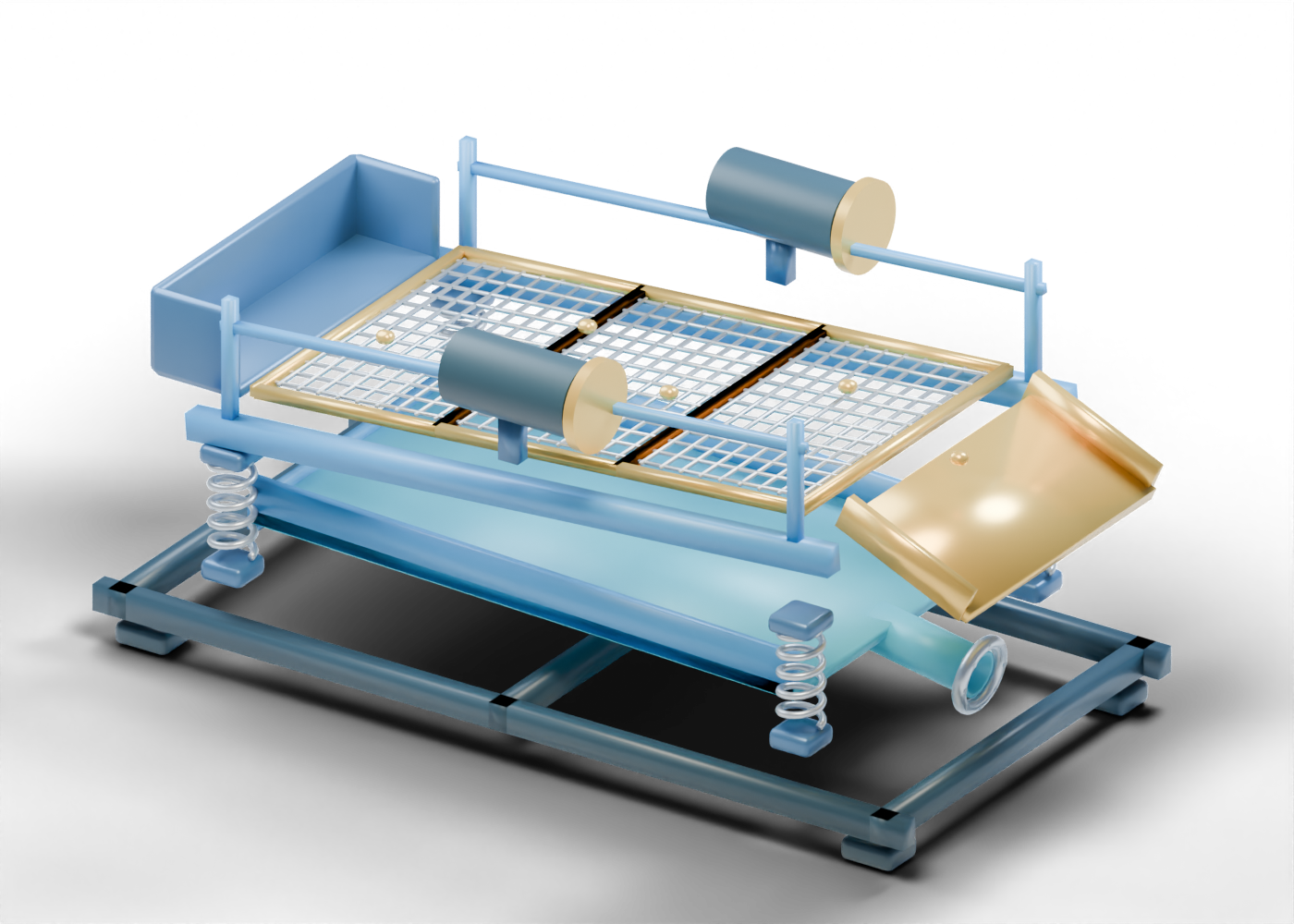
Explore an original 76-part open-screen model to distinguish the return feed, coarse cuttings exit and under-screen fluid collection without assuming a screen grade or waste approval.
Read the illustrated guideFacilities
Use an original 175-part 3D scene to distinguish free-water draw, deoiling, media polishing and open disposal boundaries without mistaking a model for measured water quality.
Read the illustrated guideFacilities
Trace an original 424-part facility scene from an incoming stream through separate oil, water and gas boundaries, then learn what a real Alberta facility claim still needs to prove.
Read the illustrated guideVessels
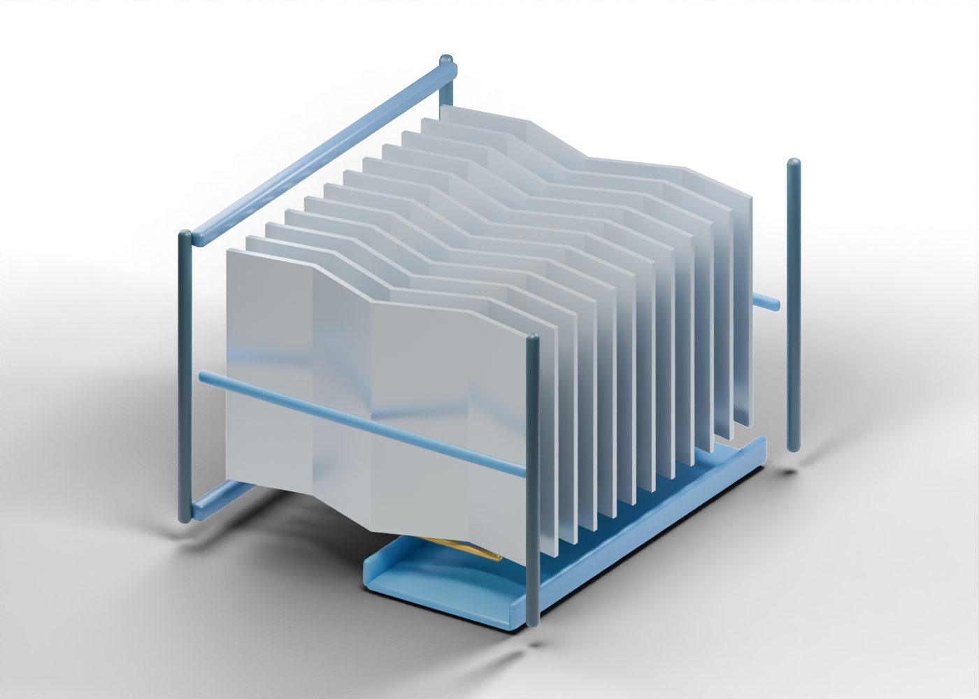
Explore an original 35-part vane pack to distinguish open gas passages, twelve separate bent plates and lower drainage locations without treating the model as a performance claim.
Read the illustrated guideVessels
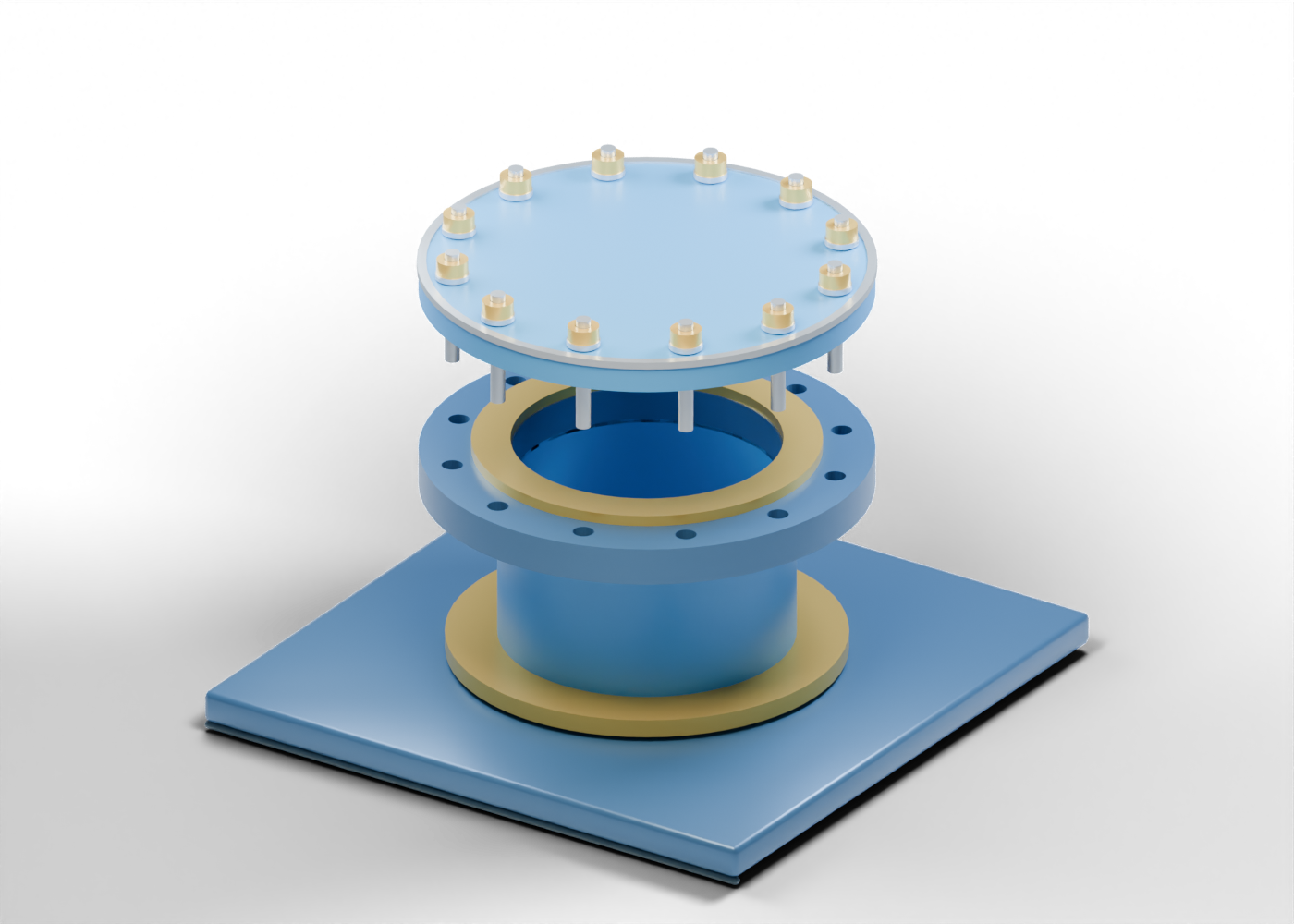
Use an original 46-part manway assembly to distinguish a wall opening, access neck, drilled flange, ring gasket, blind cover and fastener locations without mistaking geometry for a pressure rating or safe opening procedure.
Read the illustrated guideProcess plants
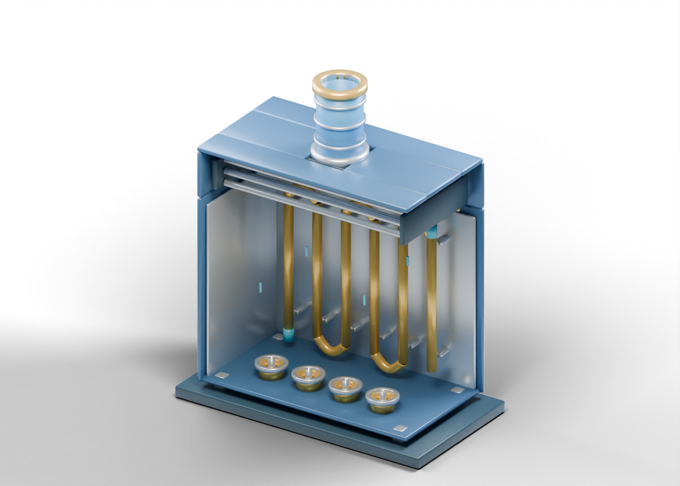
Inspect an original 94-part heater cutaway from burner locations and radiant tubes to convection tubes and an open stack, while separating visible parts from real heat-duty and safety evidence.
Read the illustrated guideOil sands extraction
Follow slurry, bitumen froth, middlings and sand-rich underflow through an original 3D teaching cutaway, and learn what an illustration cannot establish about recovery or tailings.
Read the illustrated guideOil sands extraction
Follow whole-tailings feed, a coarse-sand-rich underflow and fines-rich overflow through an original 3D teaching model while separating process roles from measured results.
Read the illustrated guideOil sands extraction
Explore the open suction, replaceable wet-end wear parts, impeller vanes, discharge and shaft-seal region of an original 3D slurry-pump cutaway.
Read the illustrated guideOil sands extraction
Use an original 3D oil-sands flotation-cell model to follow middlings, added air, secondary froth and remaining slurry without mistaking static markers for recovery data.
Read the illustrated guideOil sands extraction
Follow a generic 3D thickener from feedwell to separate water overflow and thickened-material underflow, and learn which results need measurement.
Read the illustrated guideProduction facilities
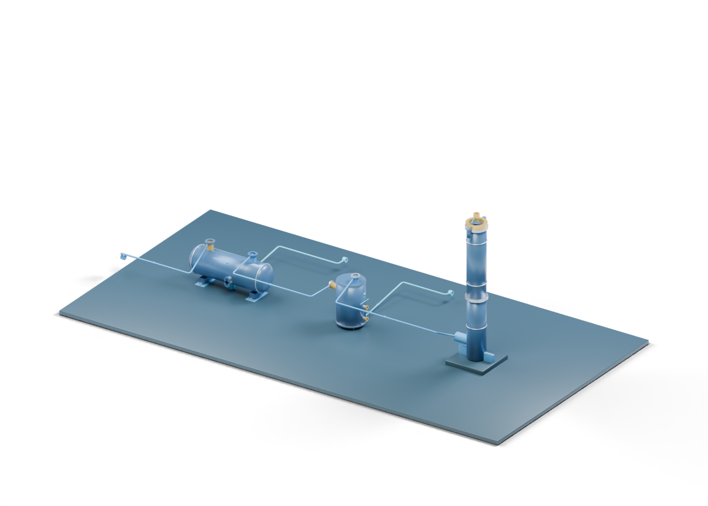
Follow an original 3D flare-system scene from an open gas header through liquid removal, a seal-vessel role and a hollow elevated stack, and learn what the picture cannot prove.
Read the illustrated guideProduction facilities
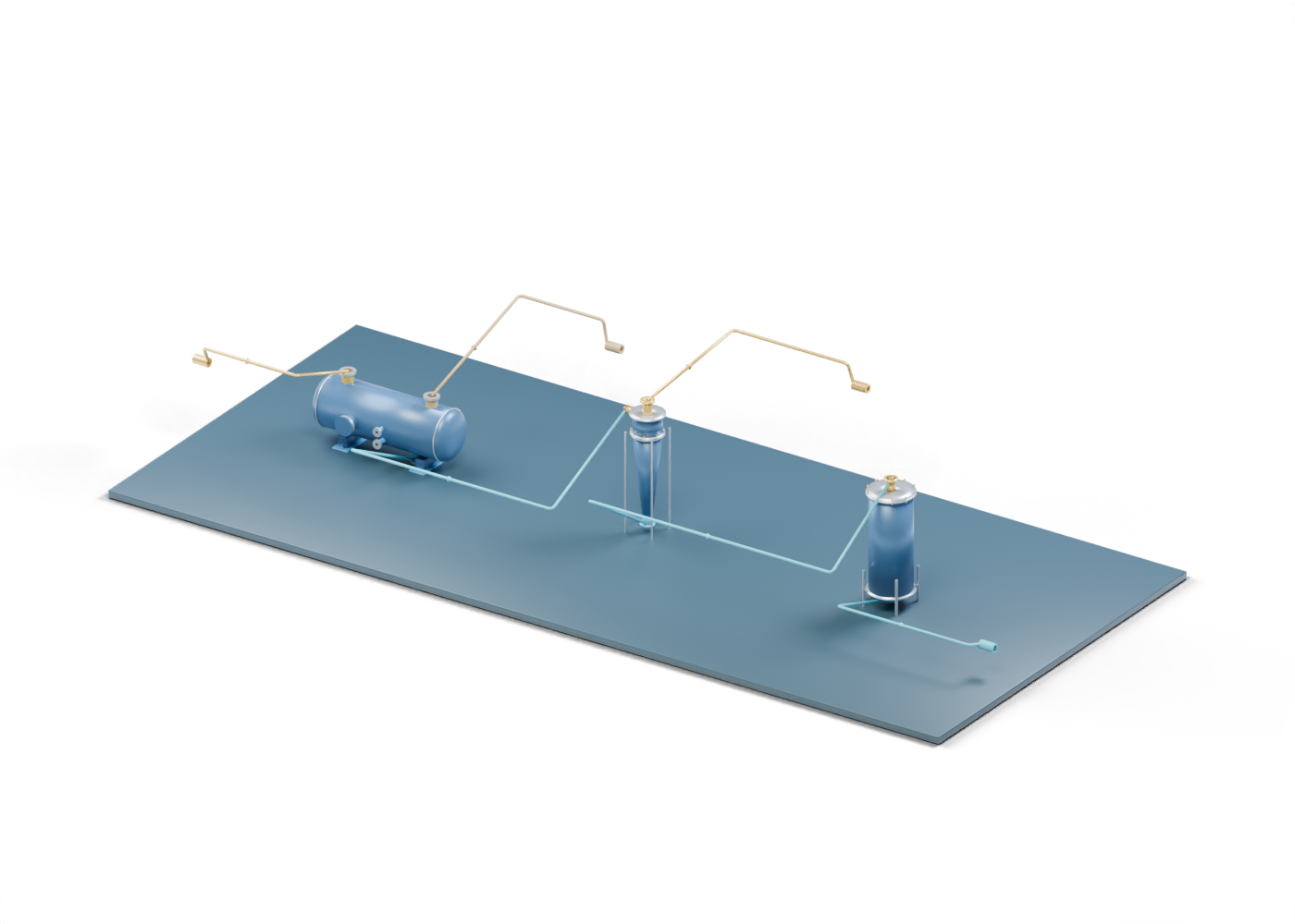
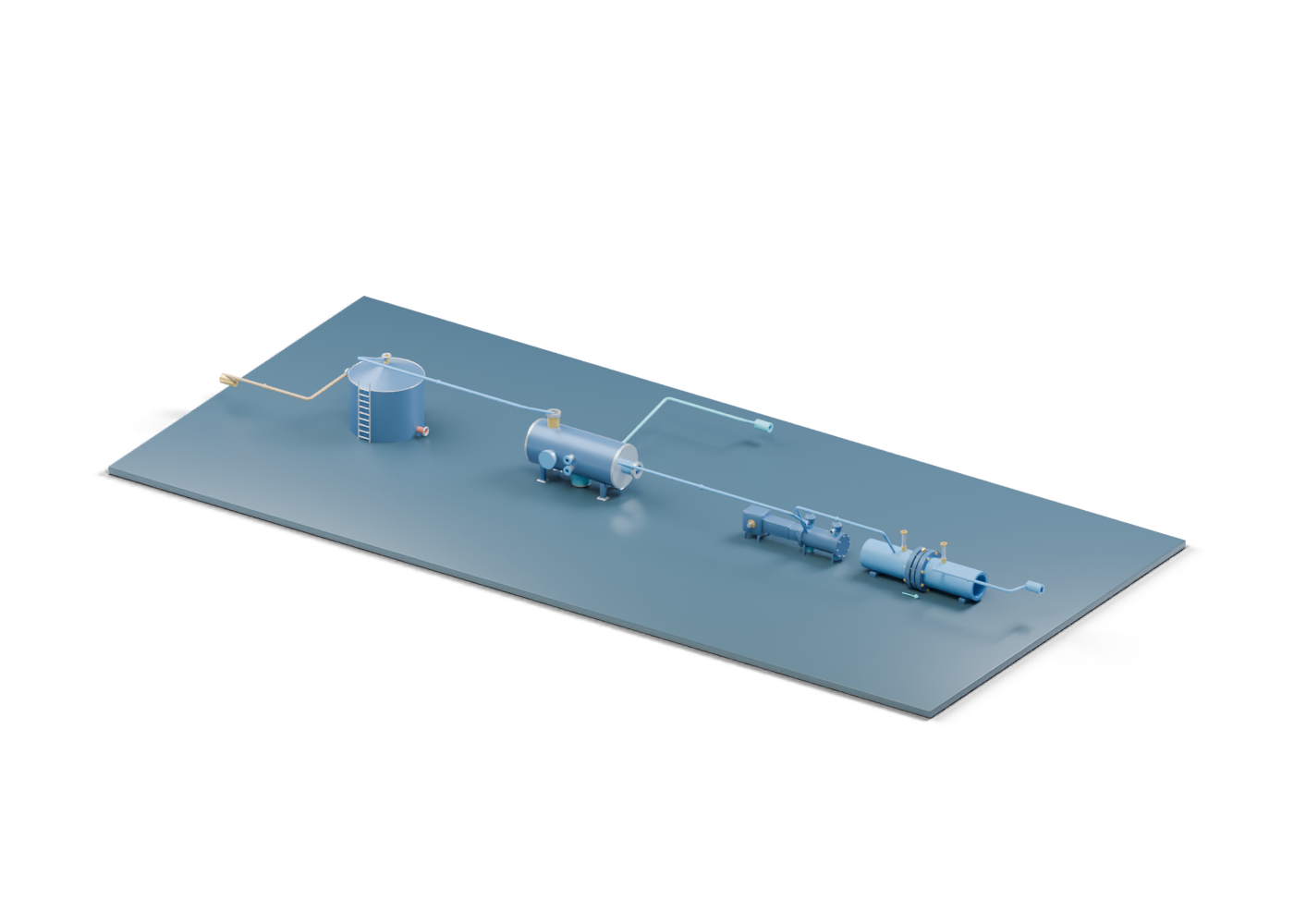
Trace an original 3D stock-tank vapour path through liquid removal, compression and a gas-handling boundary, then test what an emissions claim would need to prove.
Read the illustrated guideWell completions
Use an original 3D cutaway to distinguish the production tubing, casing annulus, sealing elements and slips without mistaking visible parts for a tested well barrier.
Read the illustrated guideProduced water
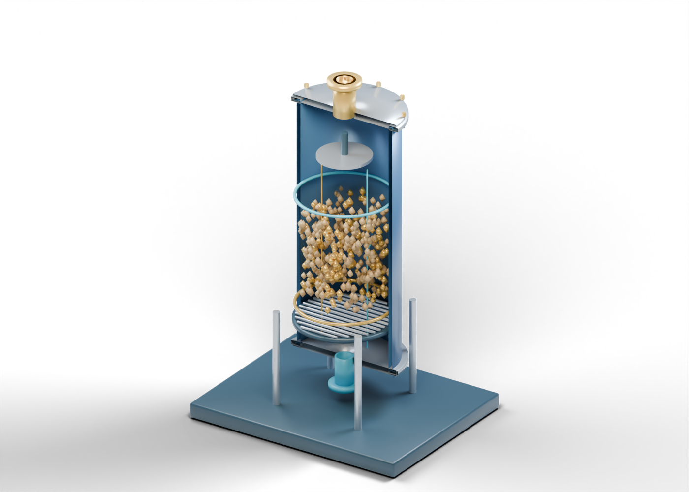
Inspect an original 3D nutshell-media filter and distinguish the visible bed, underdrain and cleaning cue from claims about outlet water quality.
Read the illustrated guideProduced water
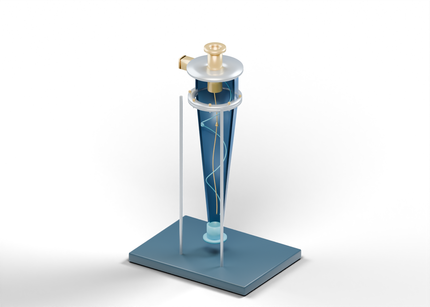
Follow a produced-water stream through an original 3D hydrocyclone lesson, then separate its visible boundaries from claims about water quality and disposal.
Read the illustrated guideProduction and separation
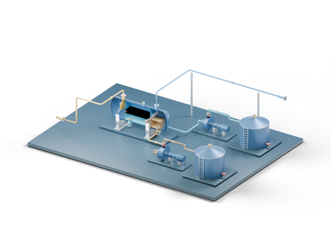
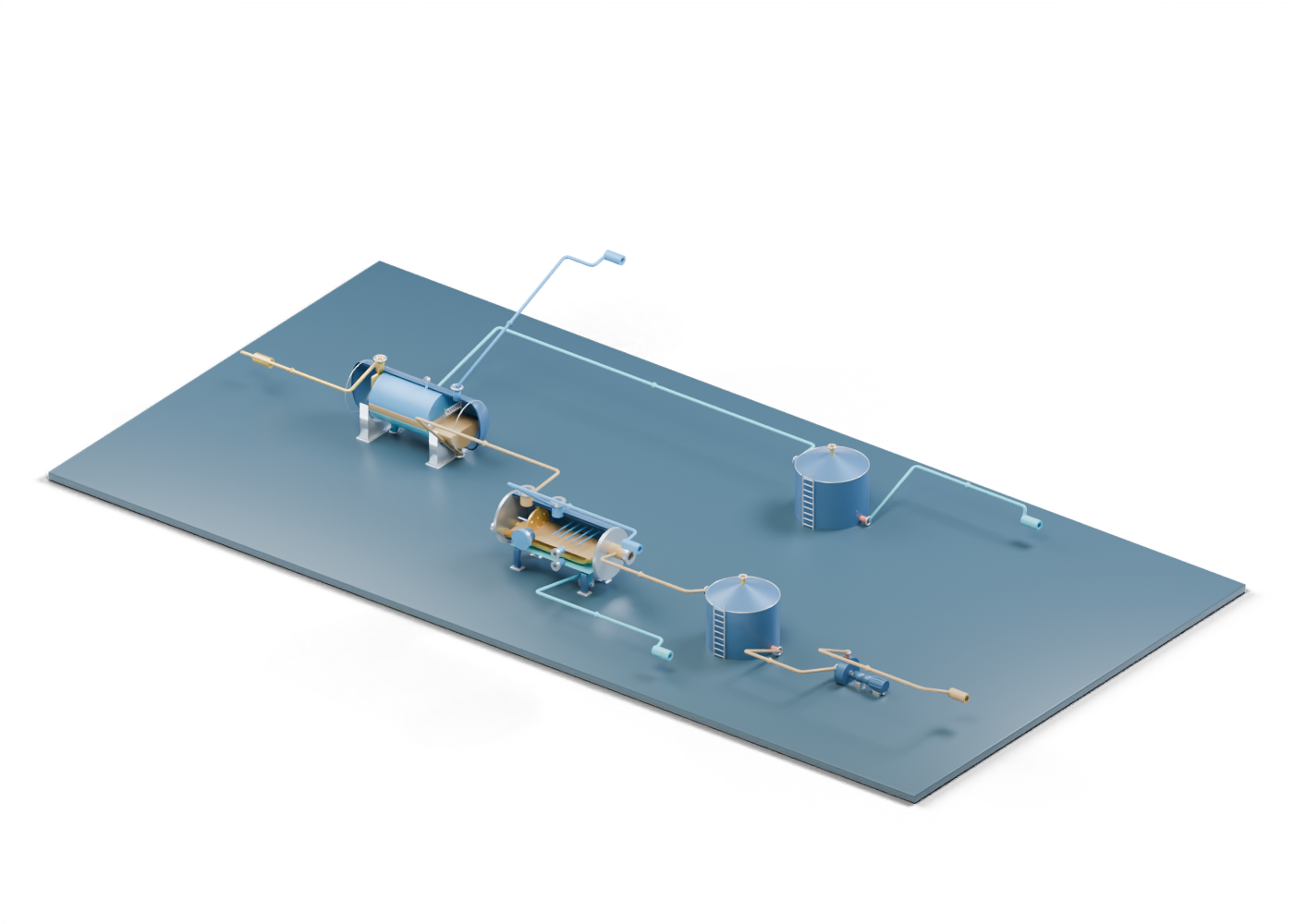
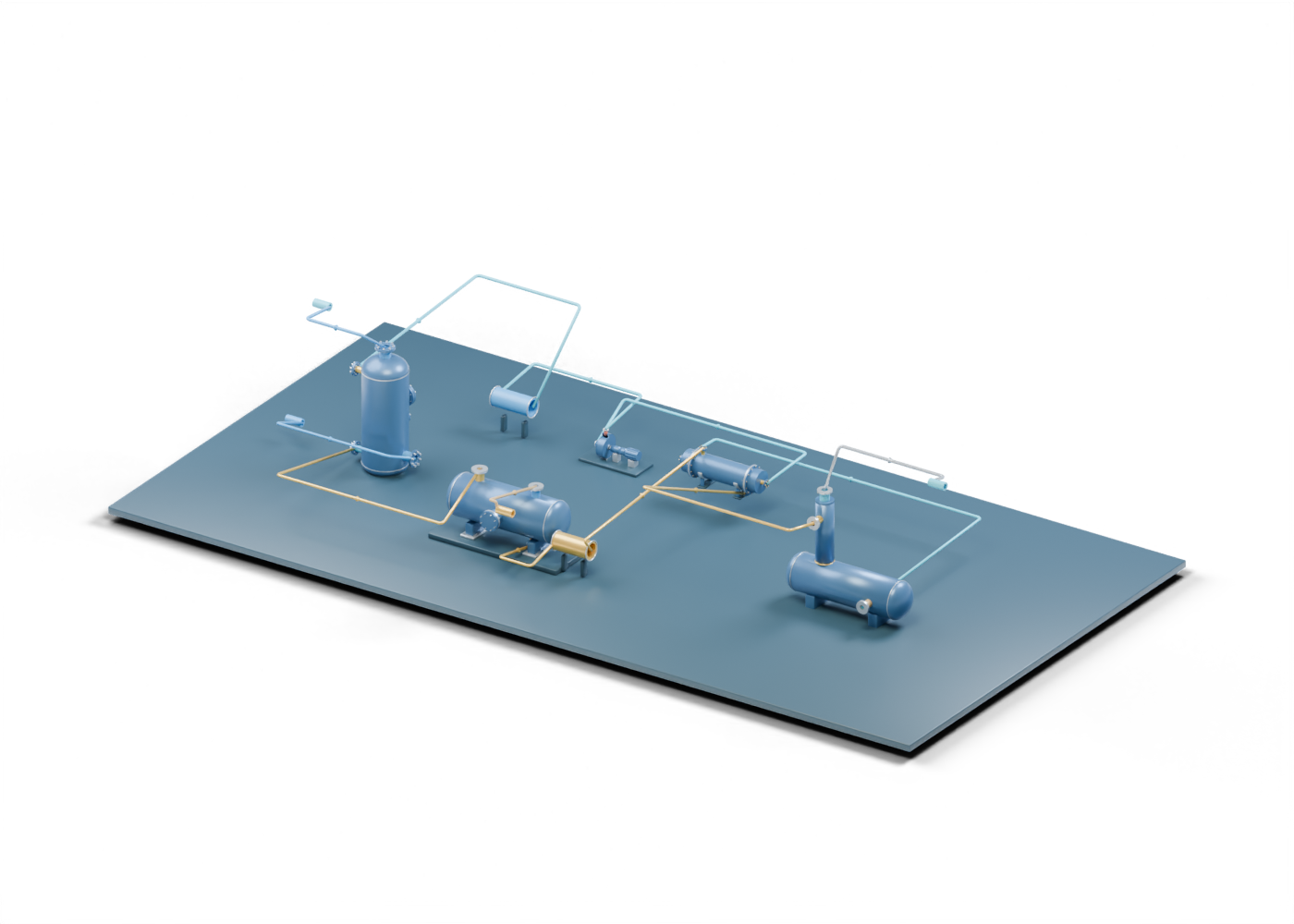
Follow an original connected 3D lesson from three-phase separation through heater treatment, oil and water storage and oil transfer, with separate open gas and water paths.
Read the illustrated guideProduction and separation
Read an original blue-and-gold 3D treater cutaway: the emulsion feed, open grid region, covered electrical location and separate oil and water boundaries.
Read the illustrated guideProduction and separation
Trace an original blue-and-gold 3D sand-separator concept from offset wellstream arrival to upper fluid outlet and lower solids collection.
Read the illustrated guideArtificial lift and pumping
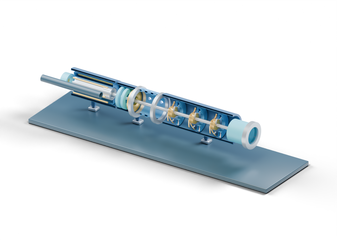
Explore an original Alberta-blue 3D ESP assembly and trace motor, protector, intake, multistage pump, discharge and cable roles.
Read the illustrated guideArtificial lift and pumping
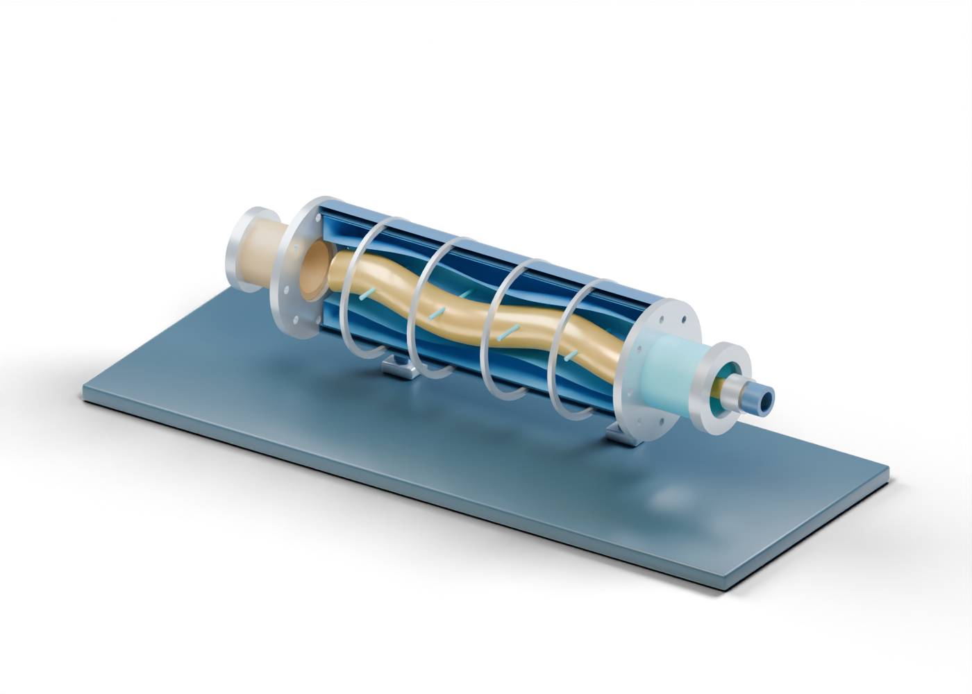
Explore an original Alberta-blue 3D rotor-and-stator model, then trace the open intake, conceptual cavity path, discharge and drive boundaries.
Read the illustrated guideProduction and separation
Explore an original Alberta-blue 3D heater-treater vessel and distinguish emulsion arrival, a heat-region cue, settling space and separate gas, oil and water boundaries.
Read the illustrated guideRefining and separation
Follow crude, wash water, a conceptual coalescence region and separate refinery outlet paths through an original Alberta-blue 3D vessel.
Read the illustrated guideGas compression and separation
Explore an original Alberta-blue 3D scrubber to distinguish inlet diversion, mist-removal location, the liquid boot and compressor-side gas exit.
Read the illustrated guideGas treatment and filtration
Explore an original Alberta-blue 3D cutaway to distinguish cartridge filtration, upper mist-removal cues, and separate gas and liquid outlets.
Read the illustrated guideGas-plant inlet and separation
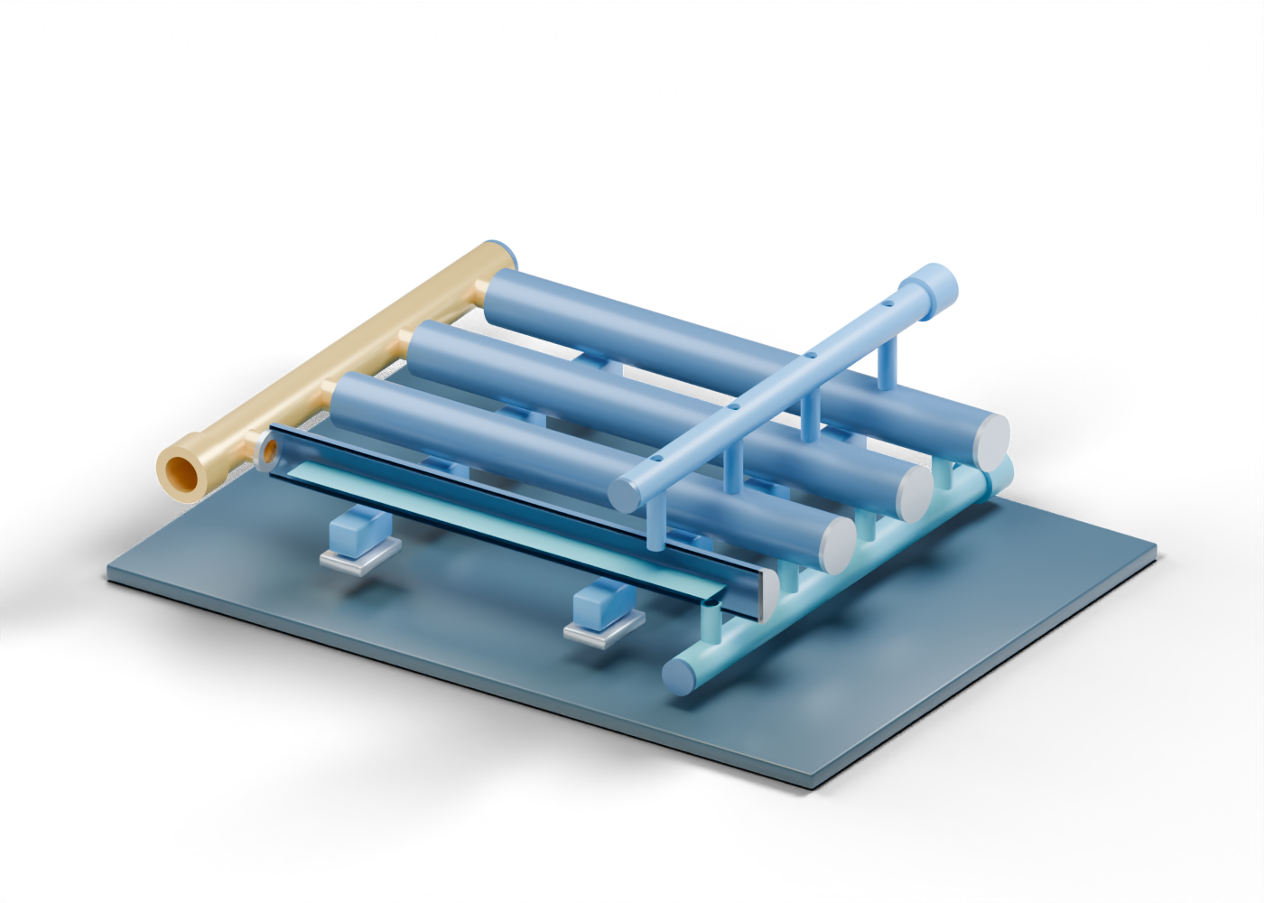
Use an original four-finger 3D scene to distinguish incoming mixed flow, upper gas collection and separate liquid handling.
Read the illustrated guideSeparation and produced water
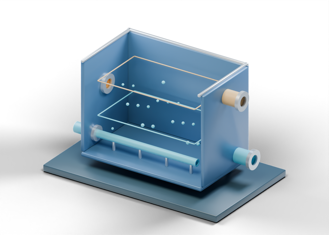
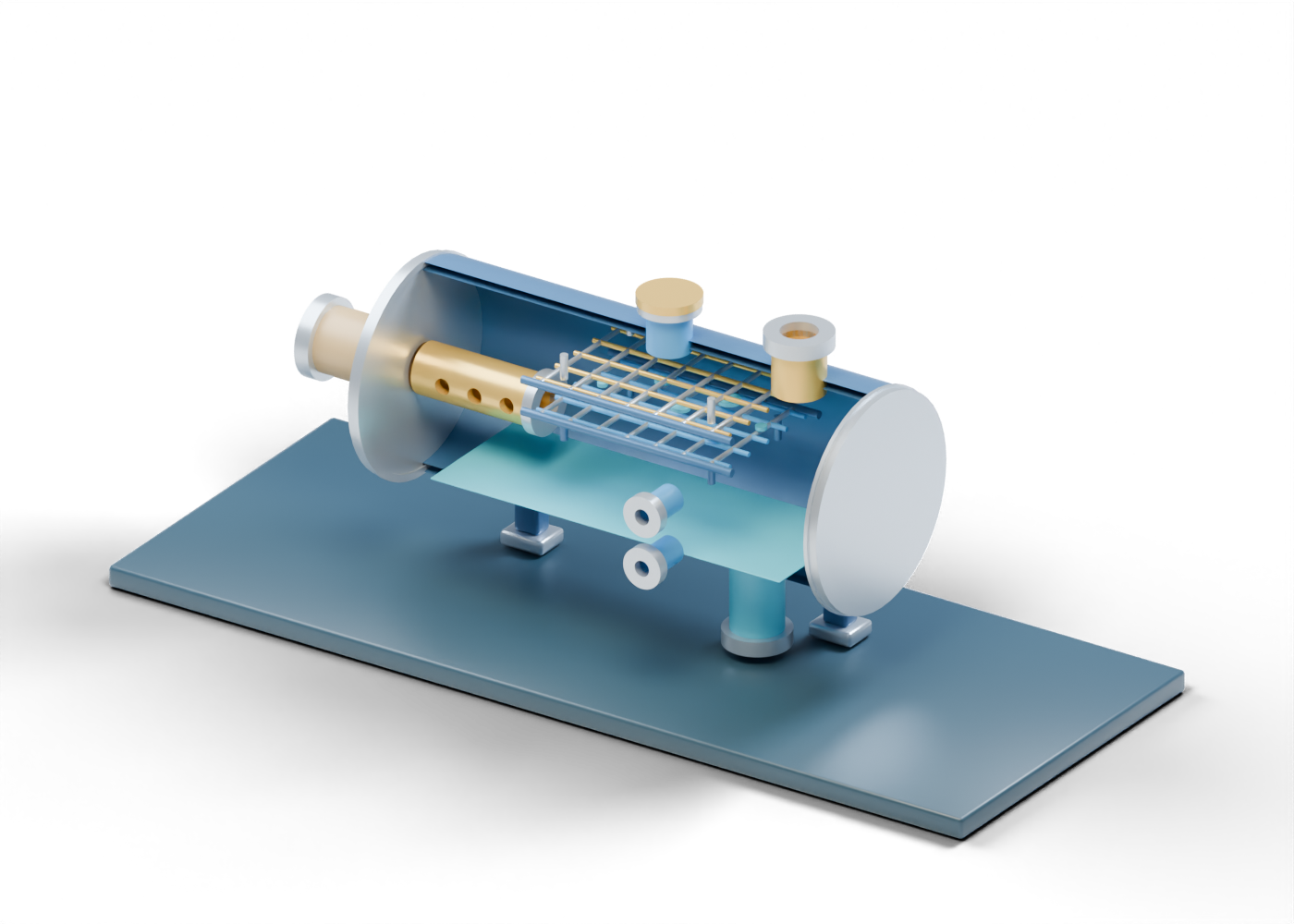
Explore an original unheated two-phase FWKO cutaway and separate free-water draw from the oil-and-gas emulsion exit.
Read the illustrated guideOil sands and production
Follow an original 3D SAGD process scene from generator to separator and well pair, with distinct liquid and produced-fluid boundaries.
Read the illustrated guideOil sands and production
Explore an original 3D steam and liquid separator and learn what its inlet, upper steam and lower blowdown boundaries do—and do not—show.
Read the illustrated guideOil sands and production
Trace water-side convection and radiant sections in an original Alberta oil-sands steam-generator cutaway while separating illustration from plant performance.
Read the illustrated guideOil sands and production
Explore an original Alberta oil-sands well-pair illustration and separate the injector, producer and conceptual steam chamber from actual project performance.
Read the illustrated guideMarket fundamentals
A practical checklist for comparing crude benchmarks, dates, delivery locations and currencies without mistaking an estimate for a market quote.
Read the illustrated guideMarket fundamentals
How to read a WTI–WCS spread, recognize the sign convention and distinguish a benchmark comparison from a producer's netback.
Read the illustrated guideProcessing and equipment
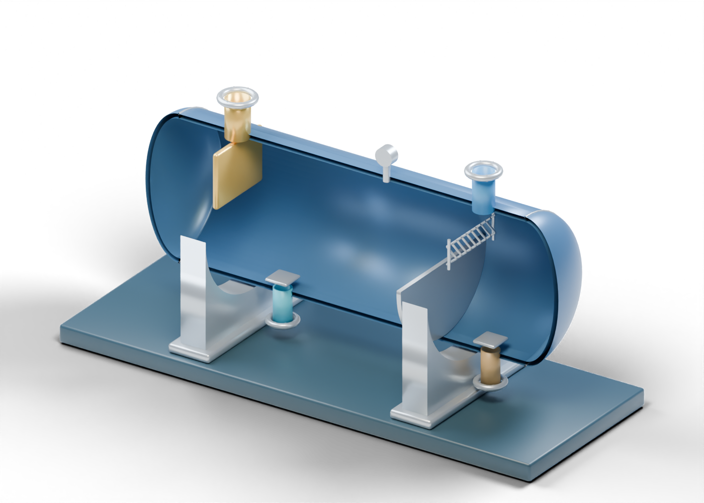
Read an original vessel cutaway, distinguish the gas, oil and water outlets, and ask better questions about processing headlines.
Read the illustrated guideProcessing and equipment
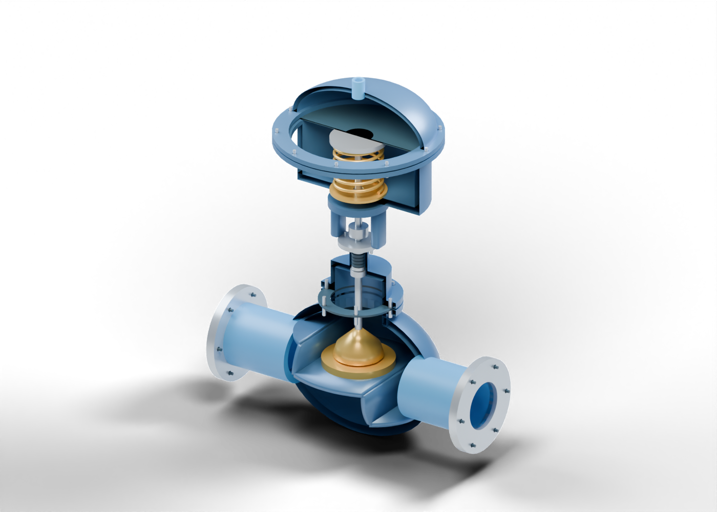
Compare three valve roles, read an original globe-valve cutaway and distinguish actuator movement from a complete process-control system.
Read the illustrated guideFUEL PRICE LITERACY
Check the period, fuel grade, unit and survey coverage before comparing a city, region or station price.
Read the illustrated guideProcessing and equipment
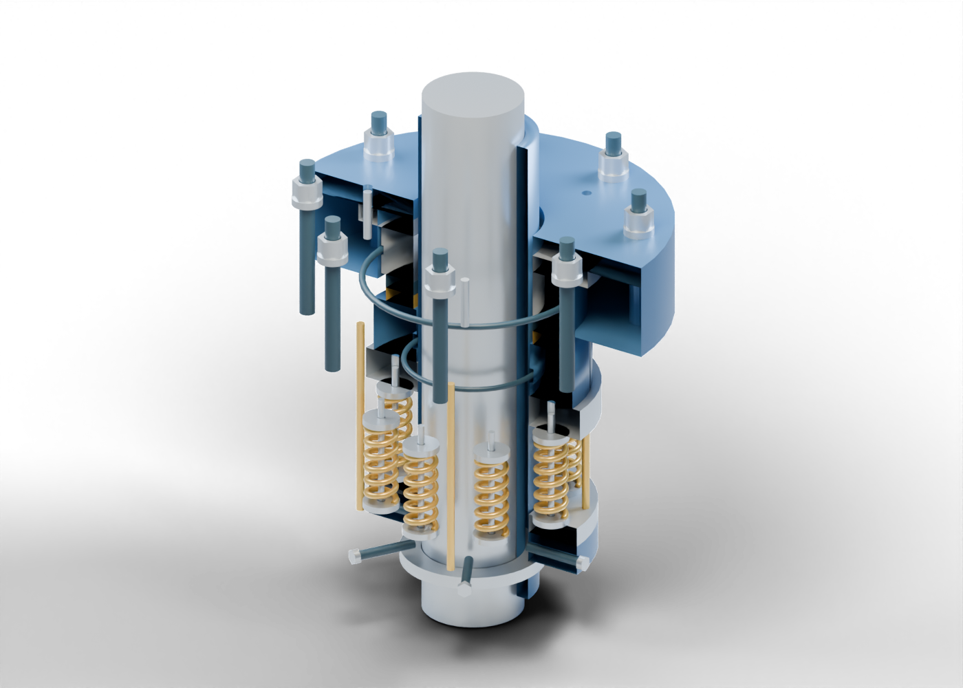
Read an original seal cutaway, separate the primary faces from secondary boundaries, and examine the evidence behind a pump-reliability claim.
Read the illustrated guideProcessing and equipment
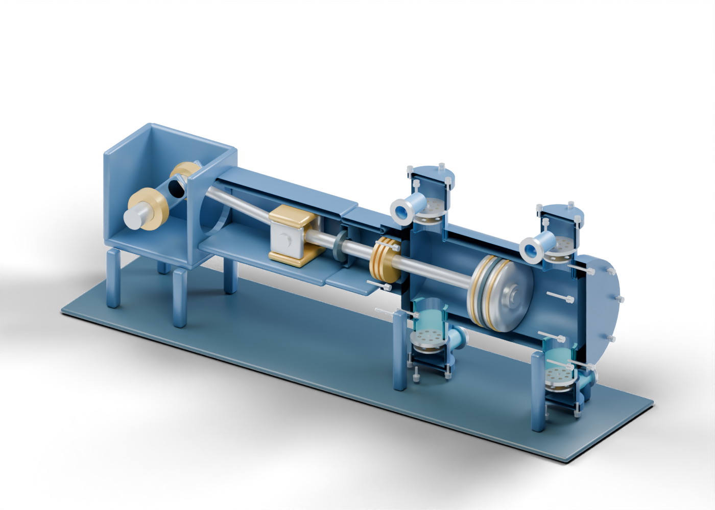
Follow the crank, crosshead, packing and piston in an original compressor cutaway, then distinguish component roles from a complete gas-compression package.
Read the illustrated guideProcessing and equipment
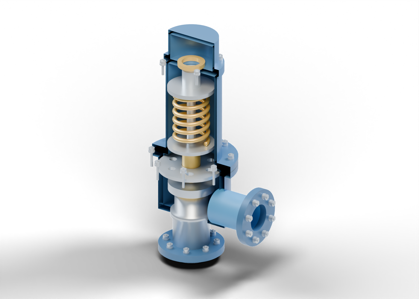
Read an original valve cutaway, trace the nozzle, disc and spring, and distinguish a pressure-protection component from a complete protective system.
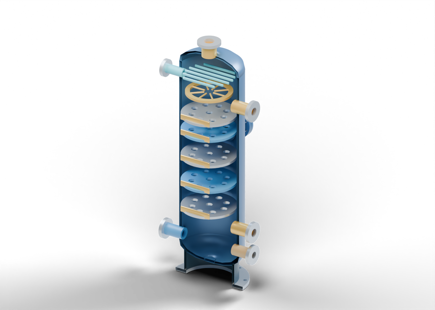
Read the illustrated guideGas treatment and vessels
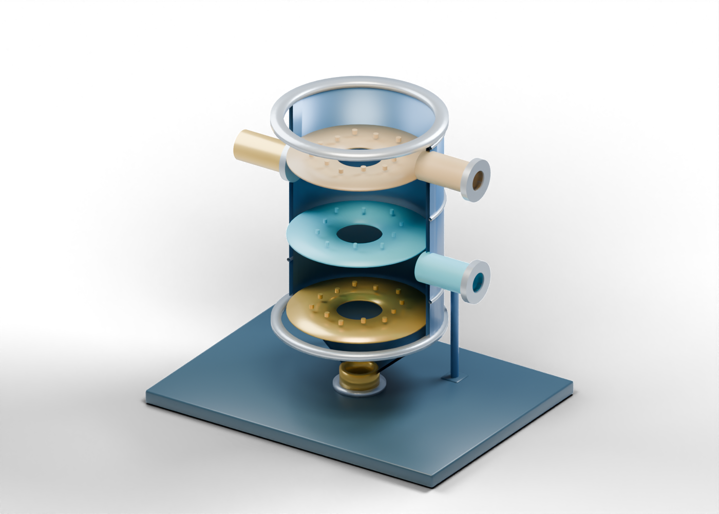
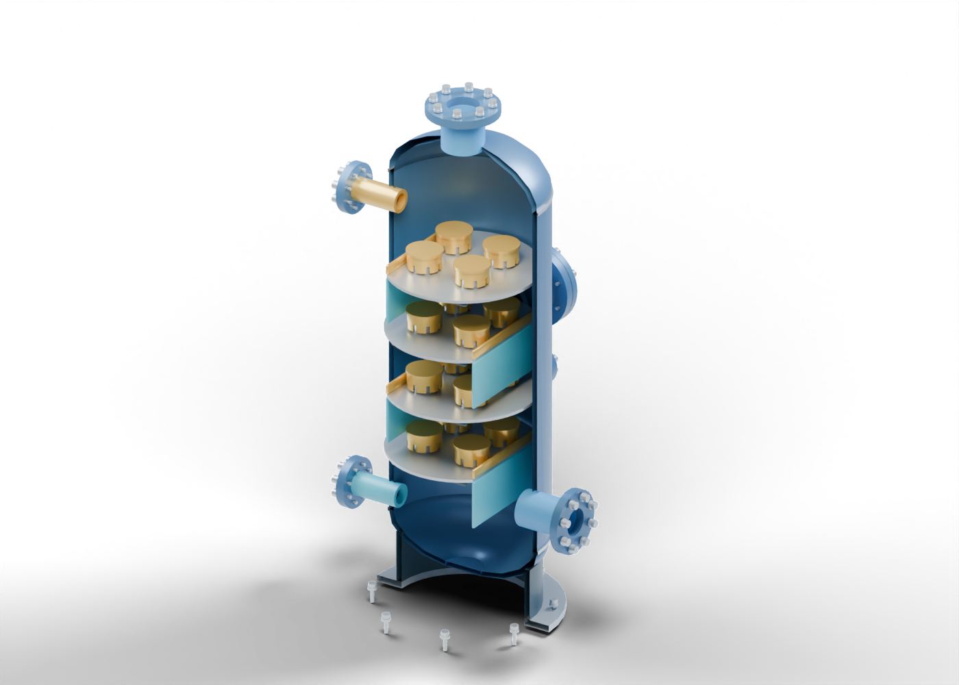
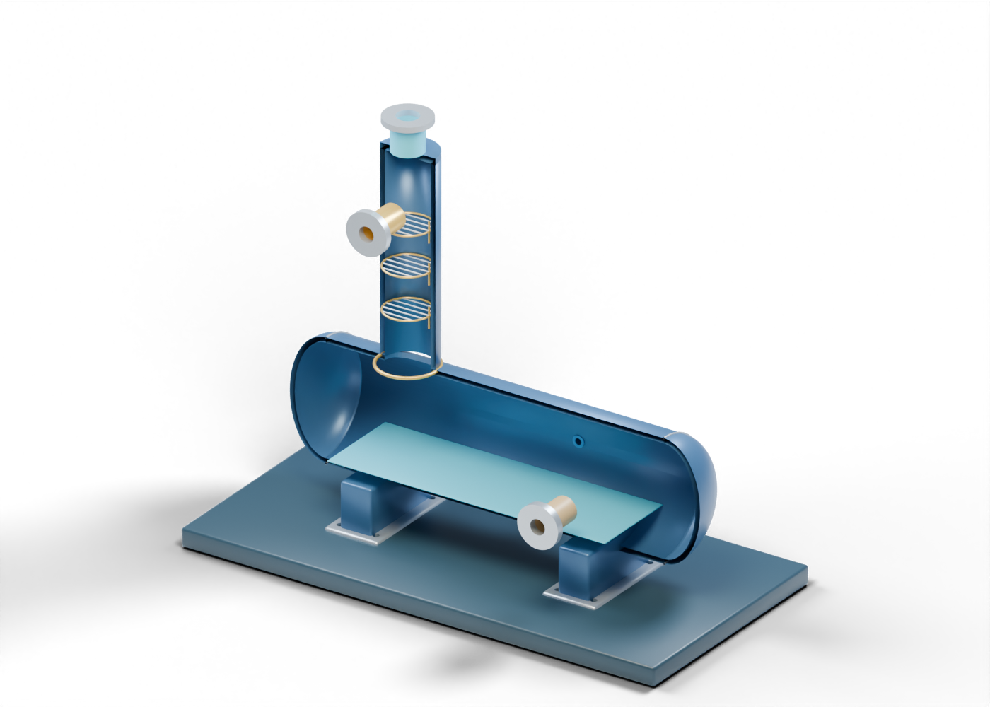
Read an original four-tray contactor cutaway, distinguish bulk separation from water-vapour removal, and identify the wider evidence behind a gas-treatment headline.
Read the illustrated guideHeat transfer and equipment
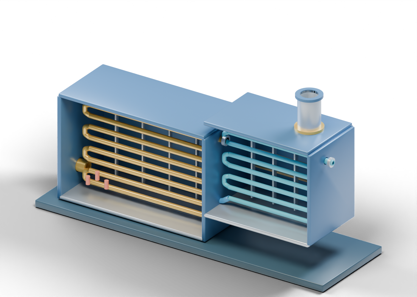
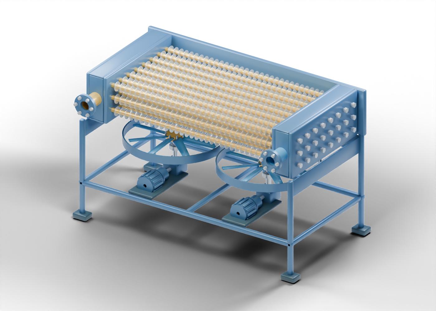
Explore an original finned-tube and fan cutaway, distinguish process flow from cooling air, and read the evidence behind a heat-transfer headline.
Read the illustrated guideGas processing and equipment
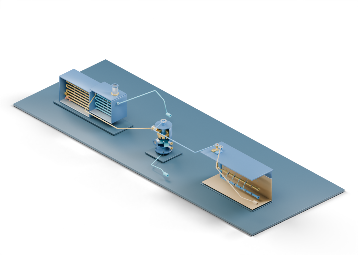
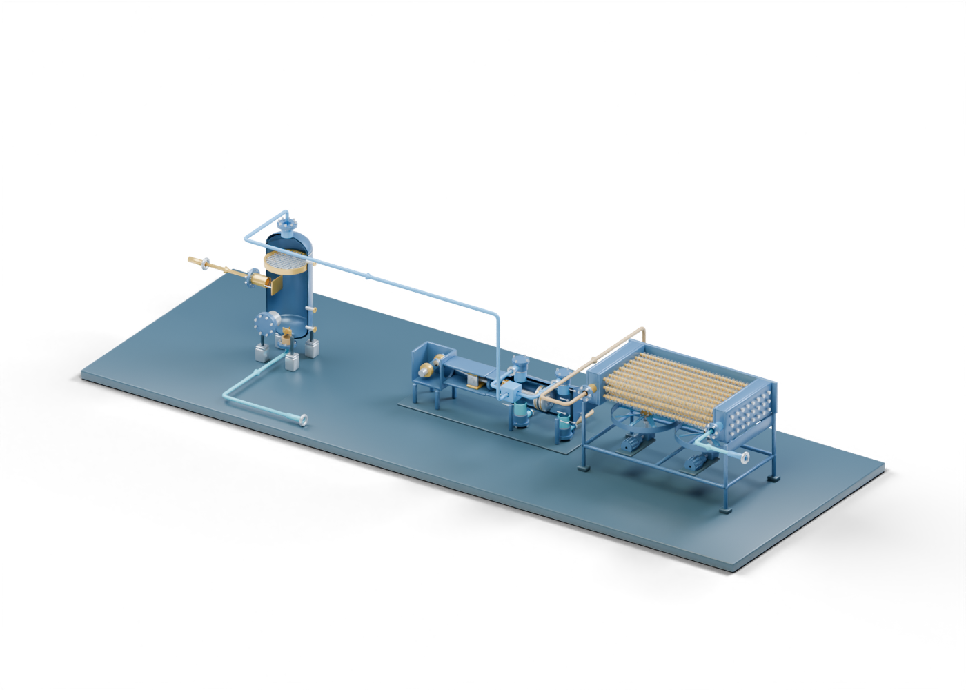
Follow an original separator, compressor and aftercooler cutaway, distinguish their jobs, and connect a plant-upgrade headline to the evidence it needs.
Read the illustrated guideValves and component boundaries
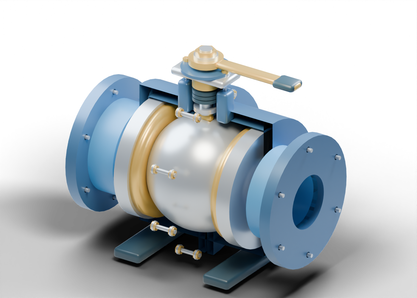
Follow the ball, curved seats, stem packing and body joint, then compare five original valve mechanisms without mistaking geometry for verified shutoff.
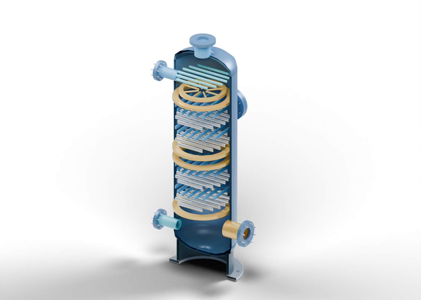
Read the illustrated guideHeat transfer and component boundaries
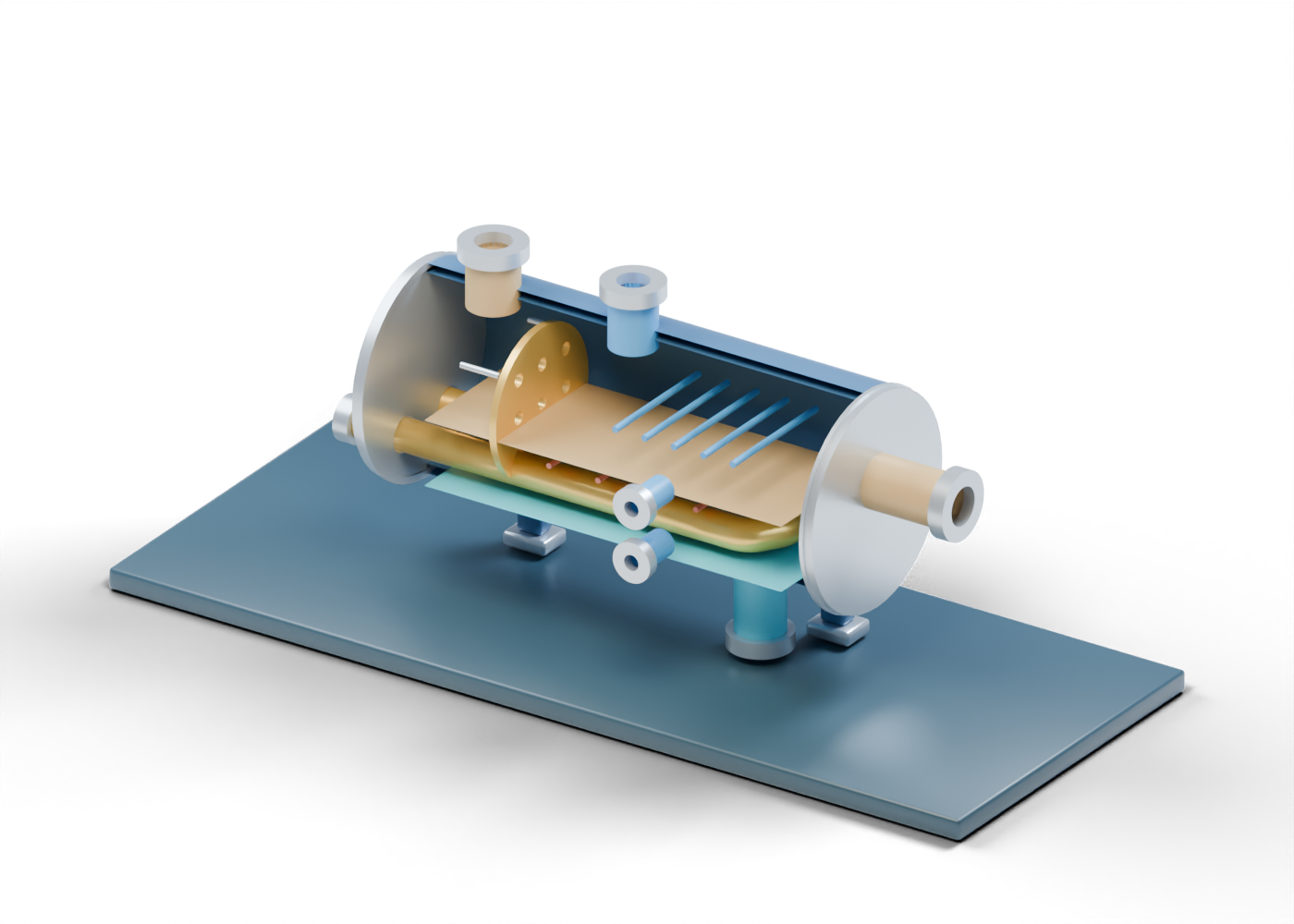
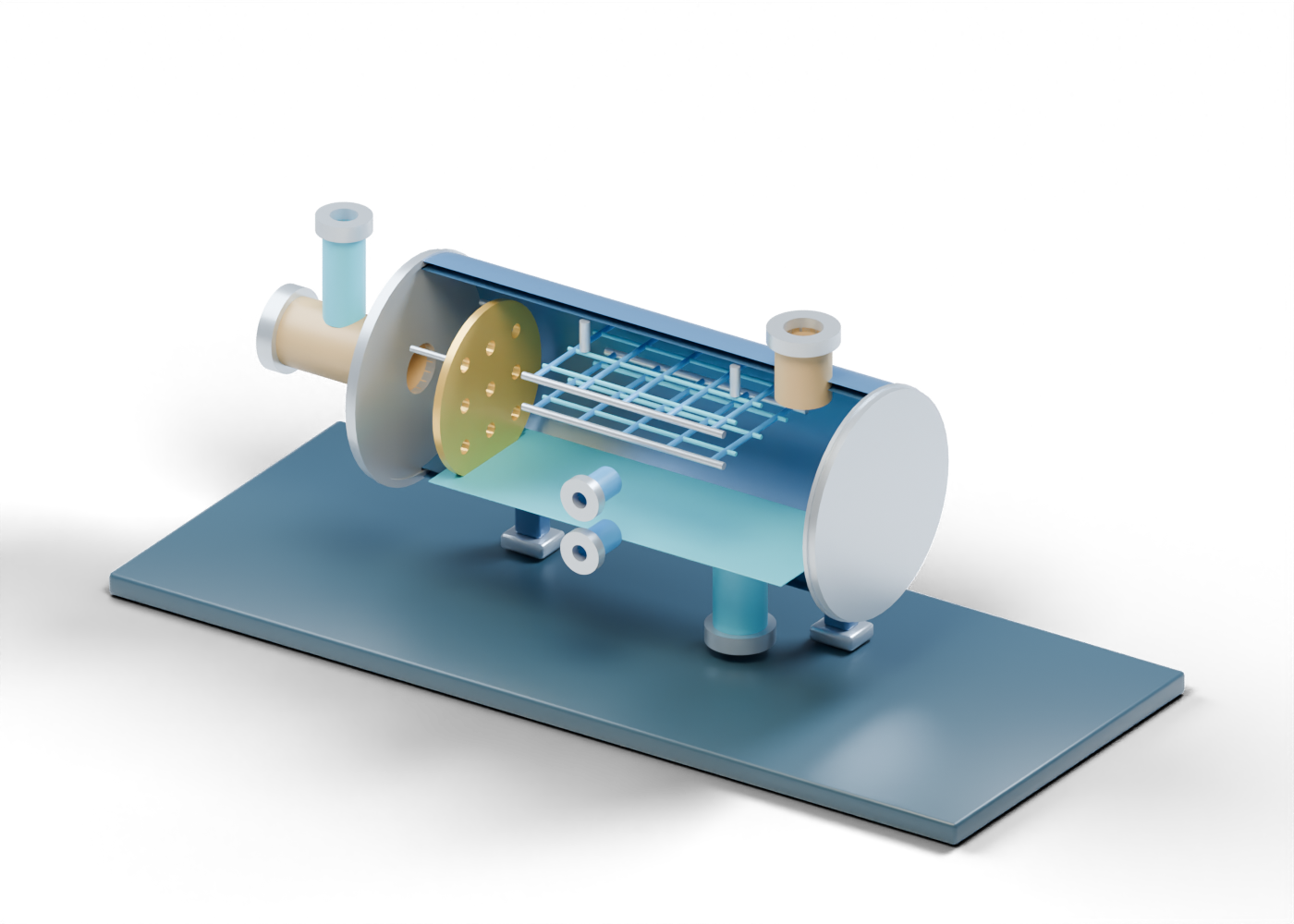
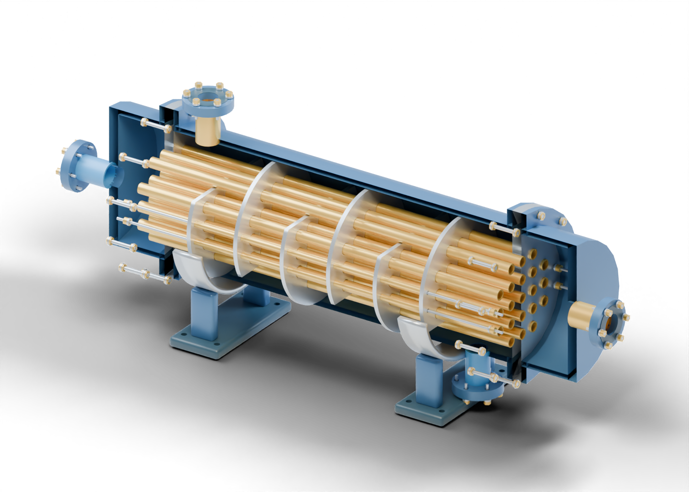
Explore hollow tubes, drilled tube sheets, alternating baffles and separate end channels in an original cutaway, then compare shell-and-tube and air-cooled heat-transfer concepts.
Read the illustrated guideSeparation and equipment evidence
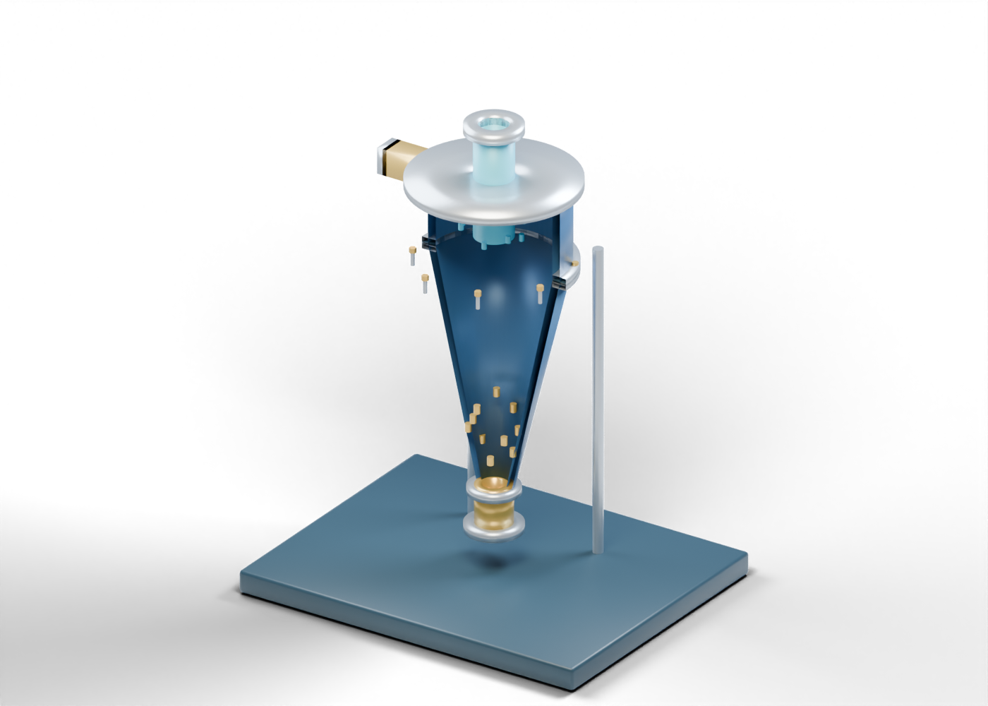
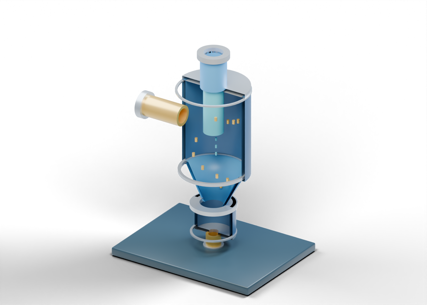
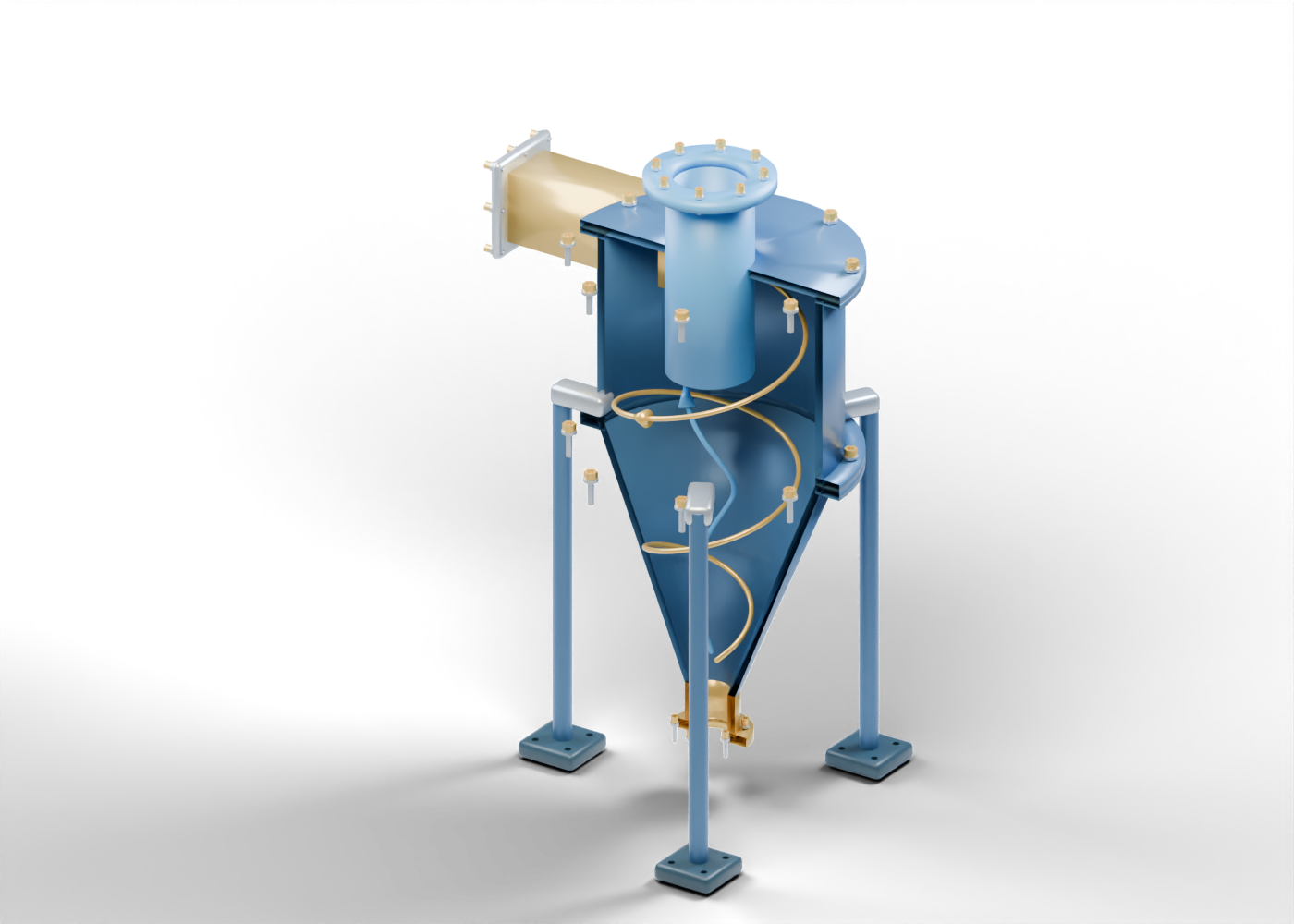
Explore an original cutaway of a cyclone body, cone and central outlet, distinguish static vortex annotations from hardware, and ask what evidence supports a separation claim.
Read the illustrated guideSeparation and equipment evidence
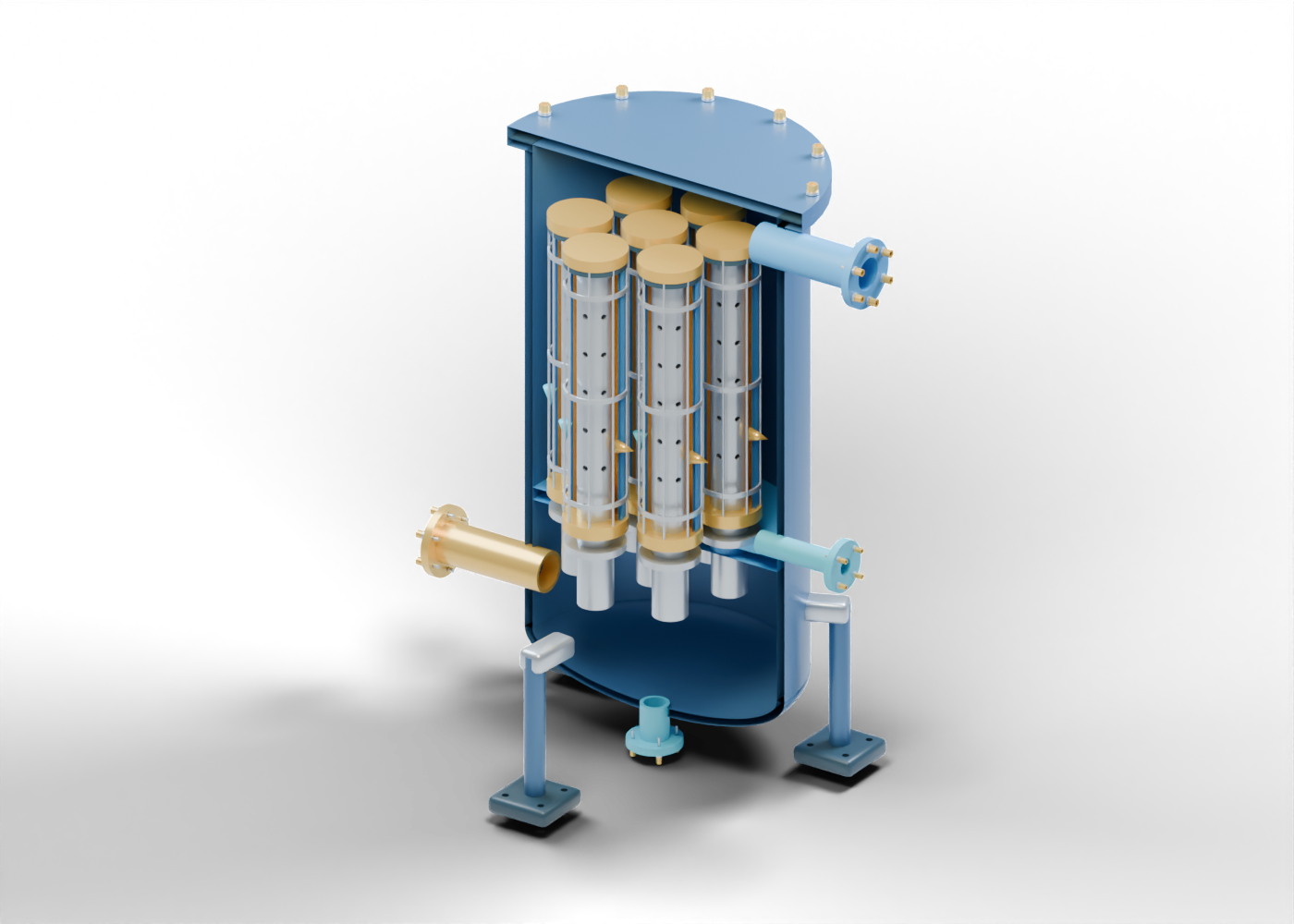
Follow seven original cartridge cores, distinguish media and drainage regions, and learn what equipment evidence can support a liquid-removal claim.
Read the illustrated guidePipeline equipment and inspection evidence
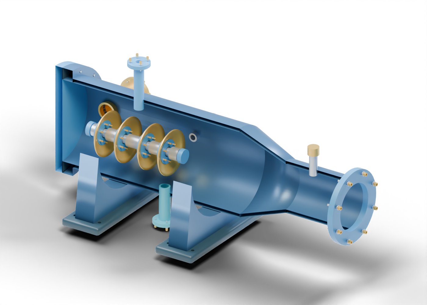
Explore the original barrel, reducer and cup-pig assembly, and distinguish visible equipment from evidence of pipeline cleaning or inspection.
Read the illustrated guideRotating equipment and reliability evidence
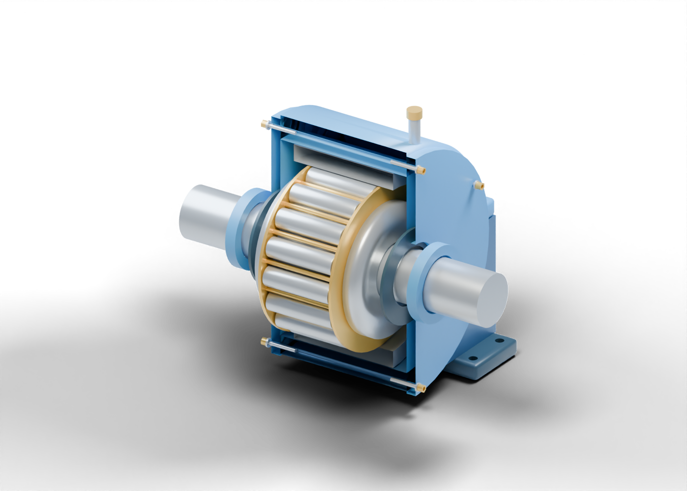
Explore rings, sixteen rollers, cage regions and a split housing, then separate a visible component from evidence of lubrication or machine reliability.
Read the illustrated guideRotating equipment and connection roles
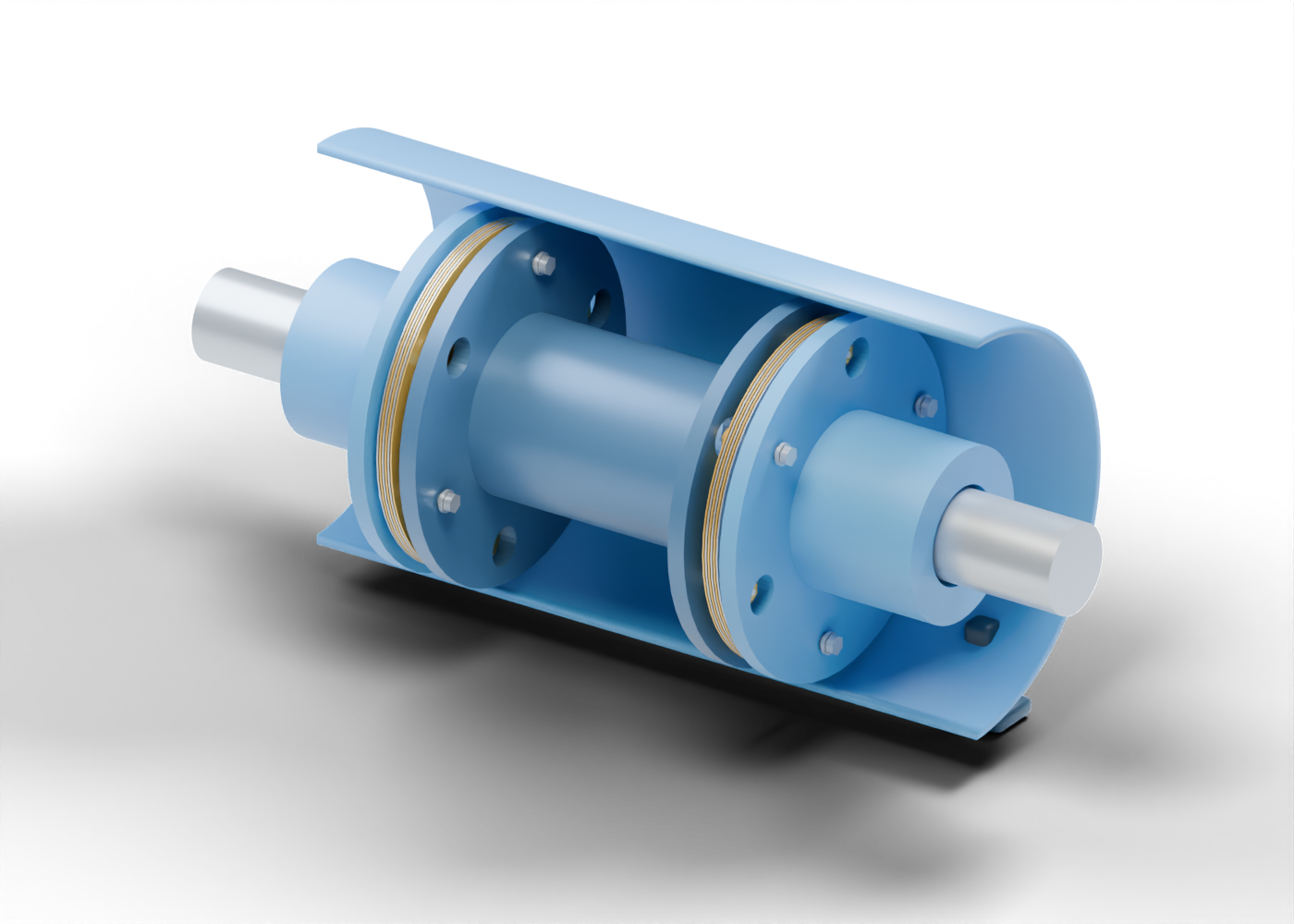
Inspect two laminated packs, alternating attachment regions, bored hubs and a hollow spacer, then distinguish visible parts from coupling and reliability evidence.
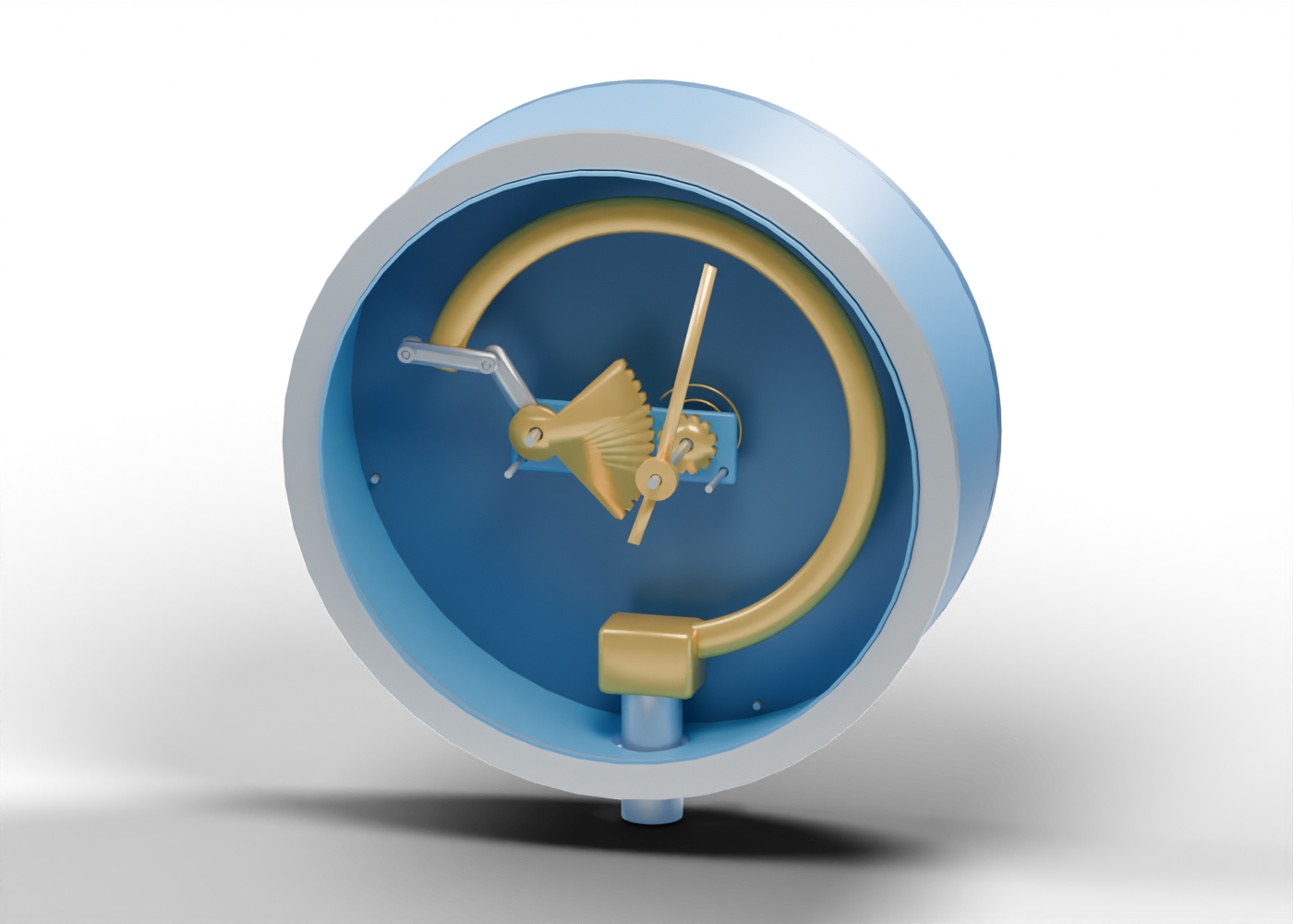
Read the illustrated guideInstrumentation and measurement evidence
Explore the oval tube and separate movement behind a pressure-gauge pointer, then distinguish visible geometry from measurement and calibration evidence.
Read the illustrated guideGas treating and process evidence
Trace the sour-gas, lean-solvent, treated-gas and rich-solvent boundaries in an original cutaway, then separate visible equipment from treating-performance evidence.
Read the illustrated guideGas treating and process evidence
Inspect an original regenerator cutaway and distinguish rich feed, lean return, reboiler interfaces and acid-gas outlet from actual process-performance evidence.
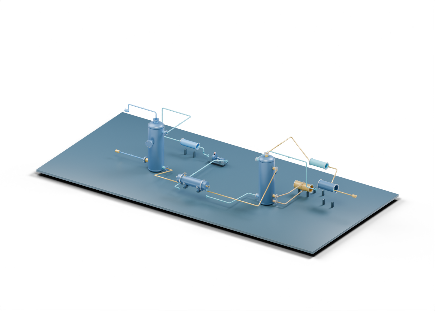
Read the illustrated guideGas treating and process evidence
Follow a source-linked original 3D teaching scene across gas, rich and lean solvent, reboiler and overhead roles without mistaking its static routes for plant engineering.
Read the illustrated guideGas dehydration and process evidence
Use an original 3D cutaway to locate rich-glycol, flash-gas and liquid boundaries, then test what the picture cannot prove about separation or emissions.
Read the illustrated guideGas dehydration and process evidence
Trace rich glycol into an original 3D still/reboiler concept and learn what an equipment render cannot establish about drying, heat or emissions.
Read the illustrated guideGas dehydration and process evidence
Follow an original 802-part 3D teaching scene from wet-gas contact through optional flashing, reconcentration and lean return, and separate visible routes from plant evidence.
Read the illustrated guideInstrumentation and measurement evidence
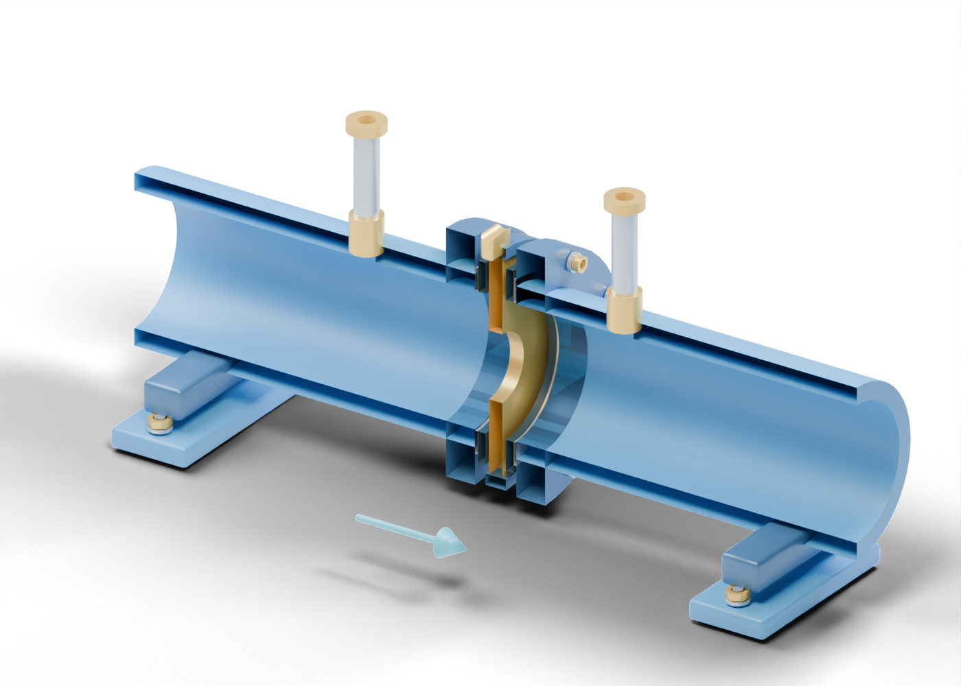
Inspect a real aperture and two separate pressure paths in an original 3D cutaway, then see what an equipment image cannot prove about flow measurement.
Read the illustrated guideFlare systems and vessel boundaries
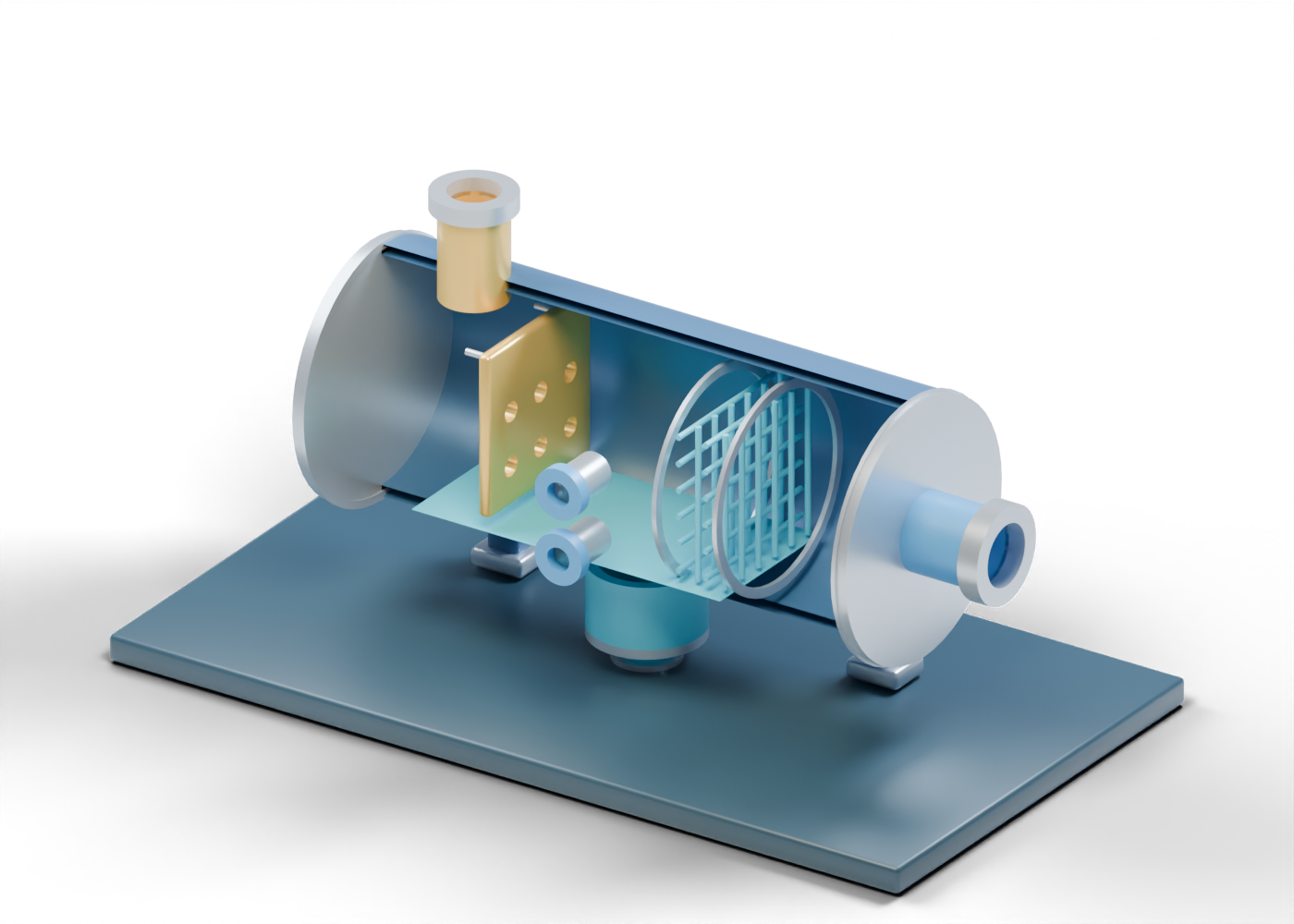
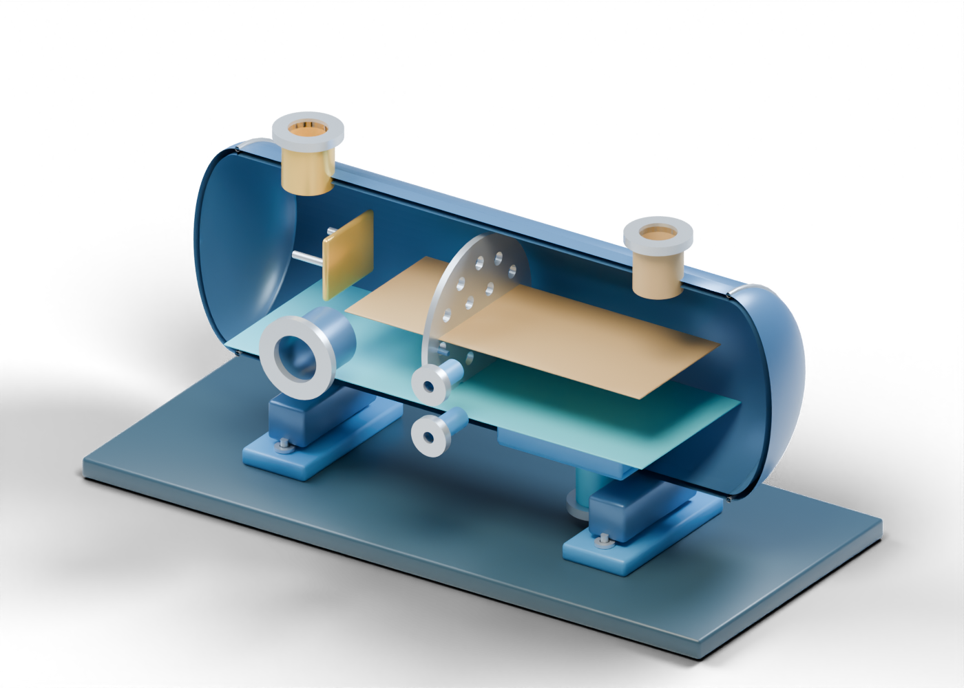
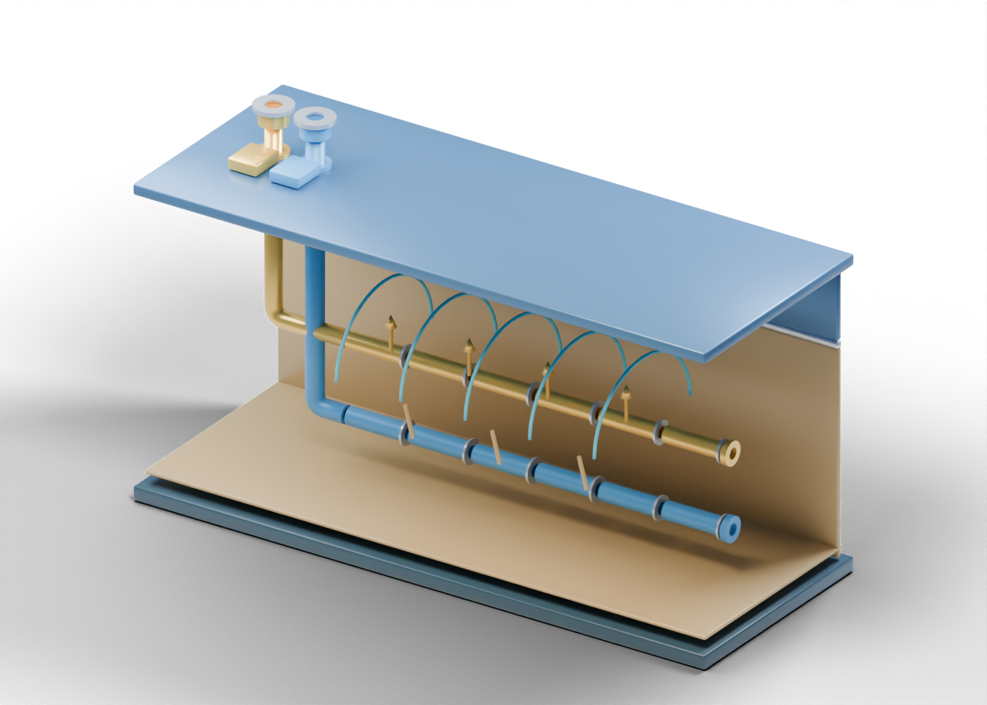
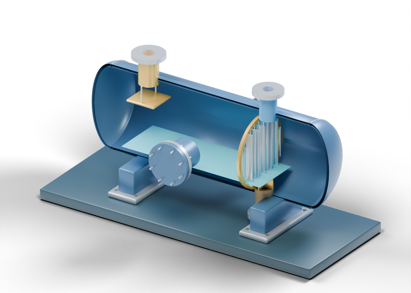
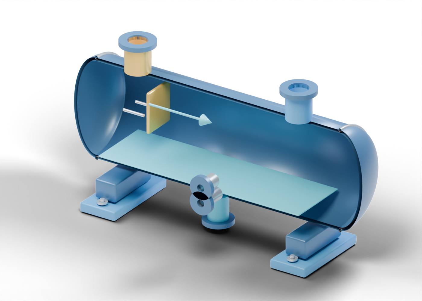
Explore an original horizontal vessel cutaway and learn what its open boundaries show—and what a flare-system claim still needs to establish.
Read the illustrated guideFlare systems and vessel boundaries
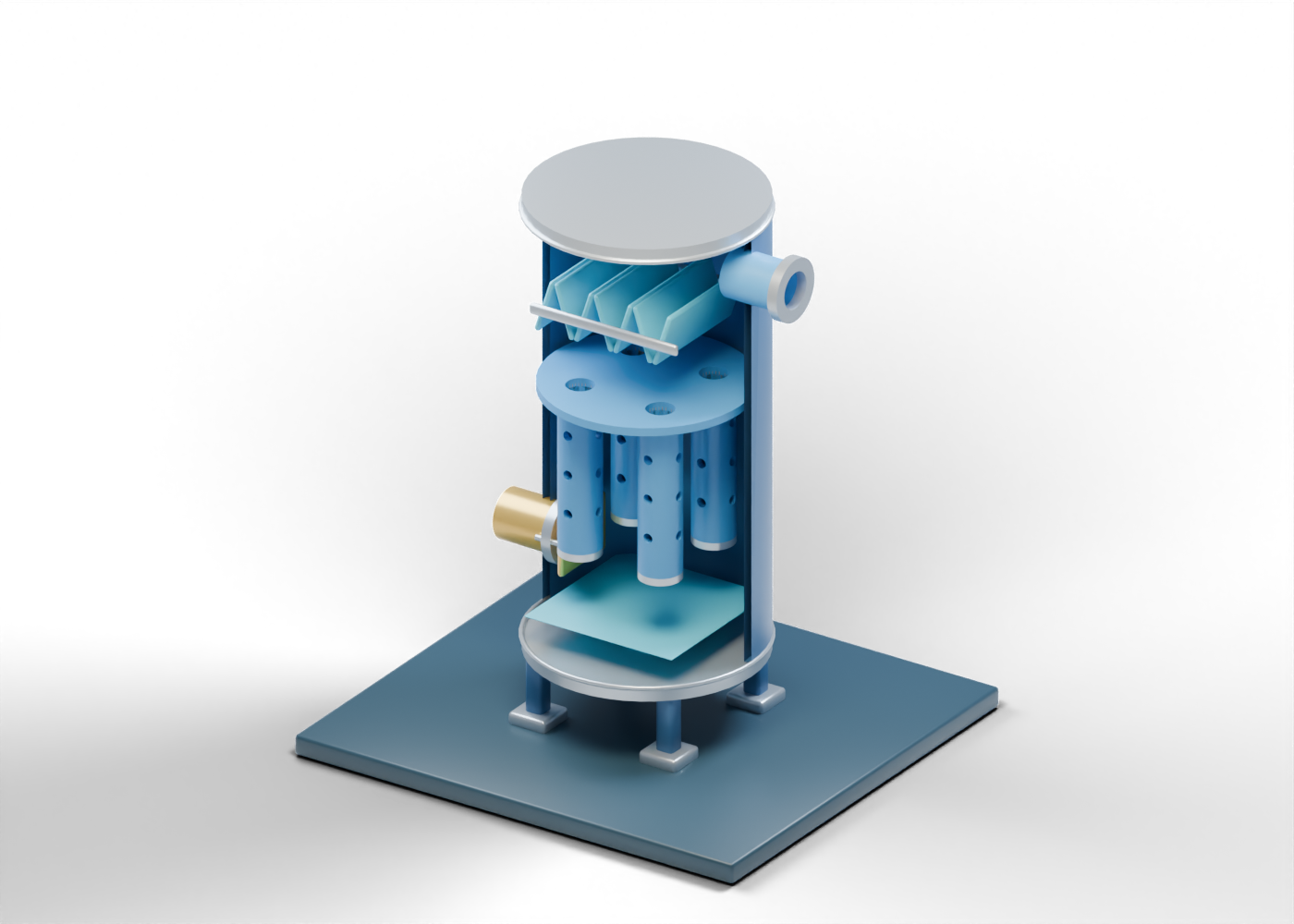
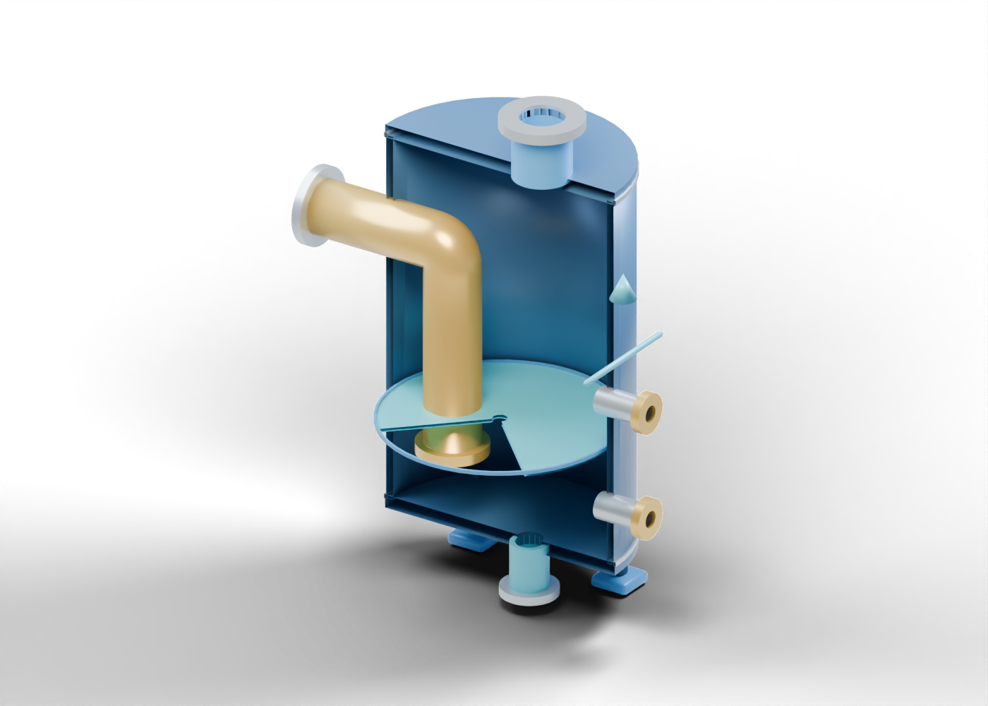
Explore an original vertical seal-vessel cutaway and distinguish its submerged inlet, gas outlet, drain and level boundaries from a proven protective system.
Read the illustrated guideA clearer vocabulary. Better questions.
Use these original component maps beside the source record, not instead of it. Interactive models show educational roles and boundaries; real equipment selections, performance and safe work need qualified, site-specific evidence.
Read the educational boundaries