1. Distinguish the vessel from the tool
A launcher introduces a pig or inspection tool into a pipeline; a receiver provides its removal location. PHMSA groups launch and receive equipment under the term trap. A cleaning pig and an instrumented inspection tool can use such equipment, but the vessel name alone does not identify the tool's capability. PHMSA pipeline glossary.
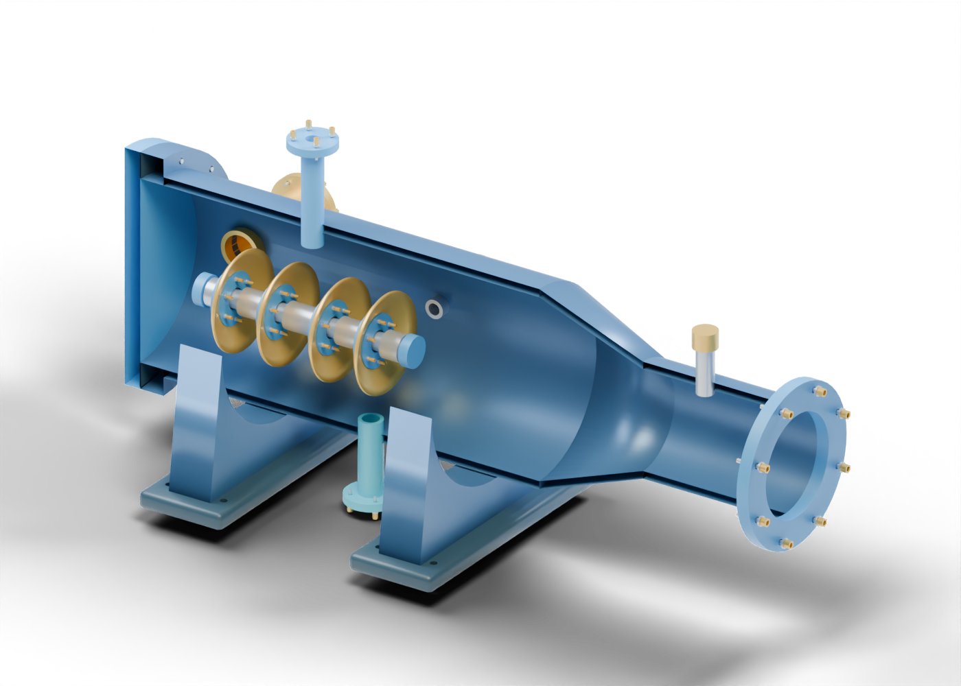
Our original assembly has 227 named mesh instances and twelve guided component studies. Its enlarged barrel contains a separate cup-pig teaching assembly. These are invented shapes, without an identified manufacturer or surveyed installation. The scene supplies no loading, opening or operating procedure.
2. Read the barrel, reducer and closure
The blue barrel joins a hollow concentric reducer and a smaller nominal spool. The reducer makes the change in illustrated bore visible; it does not supply a selected pipeline size or tool compatibility result.
At the enlarged end, a closed bolted plate and a separate gasket marker form the drawn boundary. This model has no quick-opening closure mechanism, lock, interlock or verified seal. Separating parts in the viewer is an educational display action, not an instruction for opening equipment.
Two curved saddles and drilled feet support the assembly visually. Their presence gives no foundation design, load calculation or field-installation qualification.
3. Inspect the cup assembly without inferring performance
Four flared cup envelopes surround a solid mandrel, with eight separate clamp rings, spacers and end markers. The cup bore and surrounding material are inspectable geometry. The exported tool deliberately retains radial clearance inside the invented smaller bore; there is no contact or deformation simulation.
PHMSA describes cleaning pigs as devices that remove internal debris and lists cups among possible components. That general vocabulary does not make our fixed cup shapes a cleaning demonstration. The assembly includes no inspection electronics, sensor package, recorded run or recovered-debris evidence. A real tool's capabilities require its own documentation; appearance alone cannot establish them.
4. Match visible parts to the evidence they supply
| Original component | What the teaching assembly shows | What requires separate evidence |
|---|---|---|
| Barrel, reducer and spool | Connected hollow regions with an illustrated change in bore | Selected pipeline size, tool compatibility and qualified pressure service |
| Closed plate and gasket marker | A static bolted boundary and separately named seal location | Closure design, seal contact, locking and protective arrangements |
| Cup envelopes and mandrel | Four flared shapes around a solid spine with deliberate radial clearance | Material behaviour, bore contact, travel and cleaning results |
| Clamp rings and joint hardware | Eight cup clamps and separate studs, washers and bored nuts | Actual threads, engagement, preload and qualified joint assembly |
| Connection necks and signaler envelope | Separate kicker, vent, drain and tap locations plus a closed signaler marker | Routing, isolation, instruments, passage detection and protective systems |
| Saddles and drilled feet | Two shaped supports with actual foot openings | Foundation, anchorage, loading and installation qualification |
5. Ask what supports an inspection claim
CER explains that in-line inspection uses instrumented tools to identify and measure pipeline anomalies. Different technologies address different anomaly types, and results require assessment and validation. A photograph of a trap, or a rendering of a cup-shaped tool, supplies none of that measurement record. CER pipeline integrity fact sheet.
For a news claim, distinguish the asset pictured, the tool described, the date and scope of the work, and the evidence for its reported result. Those are separate questions. This guide interprets equipment vocabulary; it neither verifies a particular pipeline nor reports a completed inspection.
6. Explore the original assembly
Open the pipeline pigging vessel for the complete model. The first flared cup selects that exact named component.
Compare the bored-ball valve lesson and the control, isolation and check-valve guide to practise separating a visible component from a claim about its function. The models are independent teaching assemblies, with no dimensionally matched installation or operational sequence.