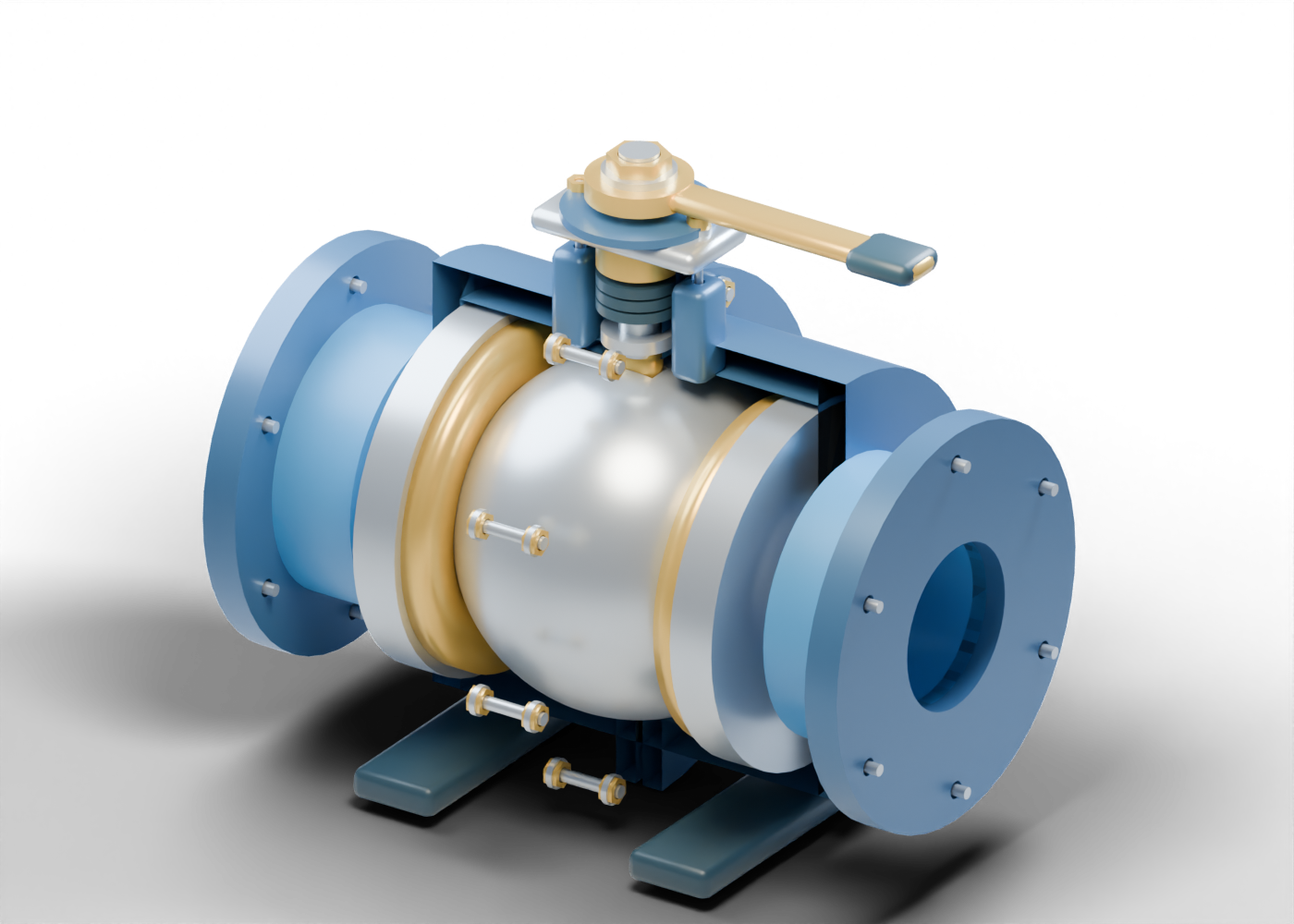
1. Look through the sphere
The closure in our original teaching model is a sphere with a real cylindrical passage. A shallow recess at its top receives a separate drive-tongue marker. The ball, stem and lever share one ten-part turning group: one pose aligns the bore with the two end connections, while a ninety-degree turn places a solid region of the ball across their centreline. That is a geometric comparison. No fluid, pressure, required torque or leakage is calculated.
The intact assembly has 94 individually named mesh instances, including repeated studs, washers and nut markers. Eight guided studies let readers focus on different component boundaries. The still hides selected enclosure regions to show internal parts; the interactive model retains the complete assembly.
2. Separate the seats from their supports
Two curved annular seat markers sit beside the bore, each backed by a separate support. The seat surfaces follow the invented sphere envelope with a small static gap. Visible proximity does not establish contact, compression, preload, a material pairing or leak-tightness.
The term floating ball appears in the primary reading below, but our model does not simulate pressure-driven ball displacement. It also supplies no trunnion-supported load path. Neither the model's appearance nor its lever motion establishes which real product can serve a particular duty.
3. Find three different boundaries
The ball-seat region, stem packing and split-body joint are different places in this assembly. Three annular packing markers surround the smooth stem under a separate bored follower and drilled gland bridge. A body-joint gasket lies between the two body halves. Keeping these parts separate helps a reader identify what a report or drawing is actually describing.
The joints have real geometric openings, smooth stud markers, washers and bored nut markers. They have no specified thread engagement, tightening sequence, preload, material or pressure qualification. The arrangement is an inspectable component concept, not an assembly or maintenance procedure.
4. Compare five closure mechanisms
These rows describe our separate original teaching models. They do not establish interchangeability, equipment selection or a real product's response.
| Teaching model | Closure or movement depicted | Evidence the visualization does not supply |
|---|---|---|
| Bored-ball concept | Sphere, stem and lever turn together; bore orientation changes | Leak-tight isolation, required torque or pressure-driven movement |
| Wedge gate concept | Wedge and rising stem translate relative to the bore | Wheel-turn relationship, seat loading or leakage result |
| Swing-check concept | Disc and hinge group change angle near an annular seat | Opening pressure, pressure-responsive timing or reverse leakage |
| Globe control concept | Actuated plug and stem change position relative to the seat | Control-loop tuning, flow capacity or verified failure position |
| Direct-spring relief concept | Separate closure, guide and spring regions remain visible | Numerical set pressure, calibrated response or a qualified discharge system |
Read the existing control, isolation and check-valve guide and spring-loaded relief-valve guide for their separate component boundaries. A valve name alone does not establish a complete protective or isolation system.
5. Read a product claim as evidence
When a news story mentions a valve installation, replacement or upgrade, identify the exact product and the claim being made. A proposed service, published product rating and measured field result are different kinds of evidence. Our render supplies none of those records.
Ask what document identifies the product, what test or service basis supports the claim, and whether the reported result concerns seat leakage, a stem boundary or a body joint. A handle orientation in an illustration supplies no verified field indication. Fire-test, anti-static, cavity-relief, emissions, materials and pressure-boundary claims each need their own applicable evidence; none is established here.
6. Explore the original geometry and primary reading
The Emerson-hosted floating-ball manual D103479X012 is dated April 2011 and was read September 27, 2026. Its principle-of-operation section connects the lever and ball with quarter-turn vocabulary; its component listing distinguishes ball, seat, stem, packing and gasket. This is a product-specific reference. Our model does not reproduce that product, its materials, ratings, performance or instructions, and no manual figures or product dimensions were imported.
Open the bored-ball valve, wedge gate or swing-check valve to compare inspectable geometry. Focus, separation and reset return the ball model to its aligned geometric pose.
This lesson supplies no sizing, equipment selection, installation, adjustment, isolation, operating or maintenance instruction. The illustrated parts do not qualify collision clearance, contact, sealing, loads, pressure, flow, torque, emissions or manufacture.