Start with the pressure-protection role
A plant-upgrade headline can name a valve without explaining its function. Pressure relief concerns releasing fluid to limit excessive pressure. A direct-spring concept uses a mechanical spring acting through a closure; it differs from an ordinary check valve's one-way-flow role and a process-control valve's regulating role. Spirax Sarco describes nozzle, disc, spring and bonnet relationships in its steam-teaching material. Spirax Sarco: safety-valve concepts.
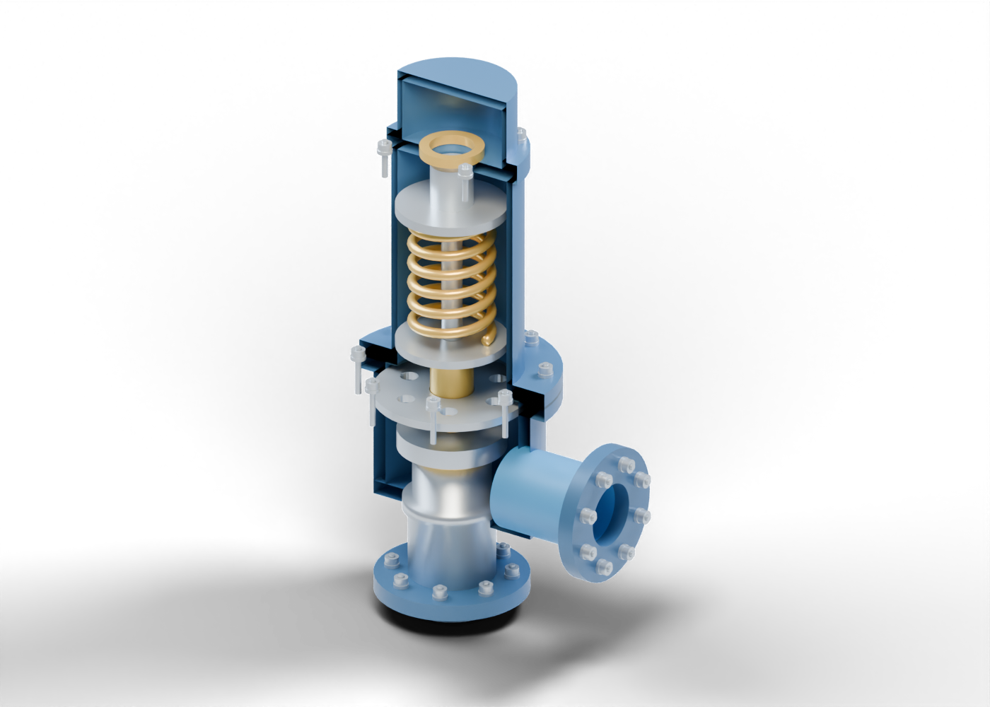
Our original illustration is a static component study. It depicts no pressure increase, automatic opening or discharge event. It does not identify the valve at a company or plant mentioned in a news report. The title uses a broad pressure-relief description without assigning a certified device class or service.
Trace the nozzle and disc
Begin at the bottom of the picture. A hollow stepped nozzle rises from the inlet region toward a separate solid disc. The disc lies immediately above the nozzle's annular upper plane in the full model. A separate bored holder and spindle-contact marker sit above it. The dark lower enclosure and lateral neck frame these components without concealing them in the cutaway.
The complete model has 109 named component instances, including repeated hardware. Its centre bores and joint holes are actual geometric openings rather than painted circles. The illustration separates an open inlet nozzle from a solid closure disc; it does not establish pressure protection performance. The visible shapes establish no sealing performance, contact load, flow capacity or opening pressure.
| Illustrated group | Relationship to recognize | Evidence still needed for real equipment |
|---|---|---|
| Nozzle and disc | Hollow inlet and separate closure surface | Actual design, certified performance and service |
| Spindle and guides | Central member through distinct bored supports | Travel, fit, alignment and force transfer |
| Coil and spring seats | Separate spring between two seat markers | Qualified spring characteristics and calibration |
| Body, bonnet and fasteners | Enclosure and attachment boundaries | Materials, threads, joint loads and pressure rating |
| Lateral neck and flange | A separate outlet boundary | Connected discharge arrangement and system evidence |
The last column identifies information absent from this teaching model. It is a way to read the picture's limits, with no equipment-selection or work procedure.
Follow the spring and its supports
The gold coil surrounds the central spindle between two separate spring-seat markers. A bored guide bushing and six-opening support plate occupy lower positions. Above the upper seat, a hollow setting-location marker, separate locking-location marker and protective cap identify different parts.
In real direct-spring devices, spring loading contributes to the closure relationship. Spirax Sarco's tutorial explains that relationship; our illustration supplies no spring rate, compression measurement or adjustment instruction. Spirax Sarco: spring-loaded component explanation.
Our coil is one closed six-turn mesh. Its selected outer envelope lies inside the invented bonnet bore. Six turns are a modelling choice, with no numerical pressure meaning. The setting marker has no thread form, movement control or calibration value. No calculation establishes force transfer through the spindle or the pictured contact marker.
Separate terminology from classification
The words relief, safety and safety relief need their source context. Spirax Sarco notes differences among terminology and standards; a headline's label alone is insufficient to classify this invented model. SLB's production glossary describes a spring-loaded relief-valve concept, including a thermal-overpressure example. That short definition does not identify the installation behind a particular news story. SLB: relief valve.
Pressure-relief designs also include different arrangements. Spirax Sarco's types overview distinguishes direct loading, bellows concepts and pilot arrangements. Those distinctions make a single generic cutaway an incomplete reference for the wider device family. Spirax Sarco: safety-valve types.
Our model omits huddling and blowdown design, bellows, pilot equipment, qualified vent/drain details, a tamper seal and a complete protective system. Its outlet stops at a flange. That endpoint supplies no downstream piping, destination, backpressure result or evidence of a qualified installation. Steam-teaching references support vocabulary here, with no Canadian code or oil-and-gas service approval.
Ask what the announcement proves
When a report describes a pressure-protection upgrade, identify its equipment boundary. Does the evidence concern a component, connected discharge arrangement or wider protective system? Does the report distinguish an announced design objective from a documented result? Which installation, conditions and observation period does that result describe?
A detailed image can make the parts easier to recognize while leaving those questions unanswered. This illustration calculates no pressure, capacity, leakage, spring force, reseating or full assembly collision. Its cutaway removes selected surfaces for visibility; it does not depict equipment opened for work. This guide provides no sizing, selection, adjustment, operating or maintenance instruction.
Explore the 3D component studies
The pressure-relief 3D model contains eight guided studies, selectable components, isolation and section views. Compare it with the control-valve 3D model to distinguish a direct-spring closure from a separate actuated plug and stem. The independent prototypes have invented proportions; they are not interchangeable parts or one matched installation.
Our control, isolation and check-valve explainer extends that comparison. Read the component's role together with the evidence about the wider system, rather than treating its appearance as proof of a project result.