1. Find two different spaces
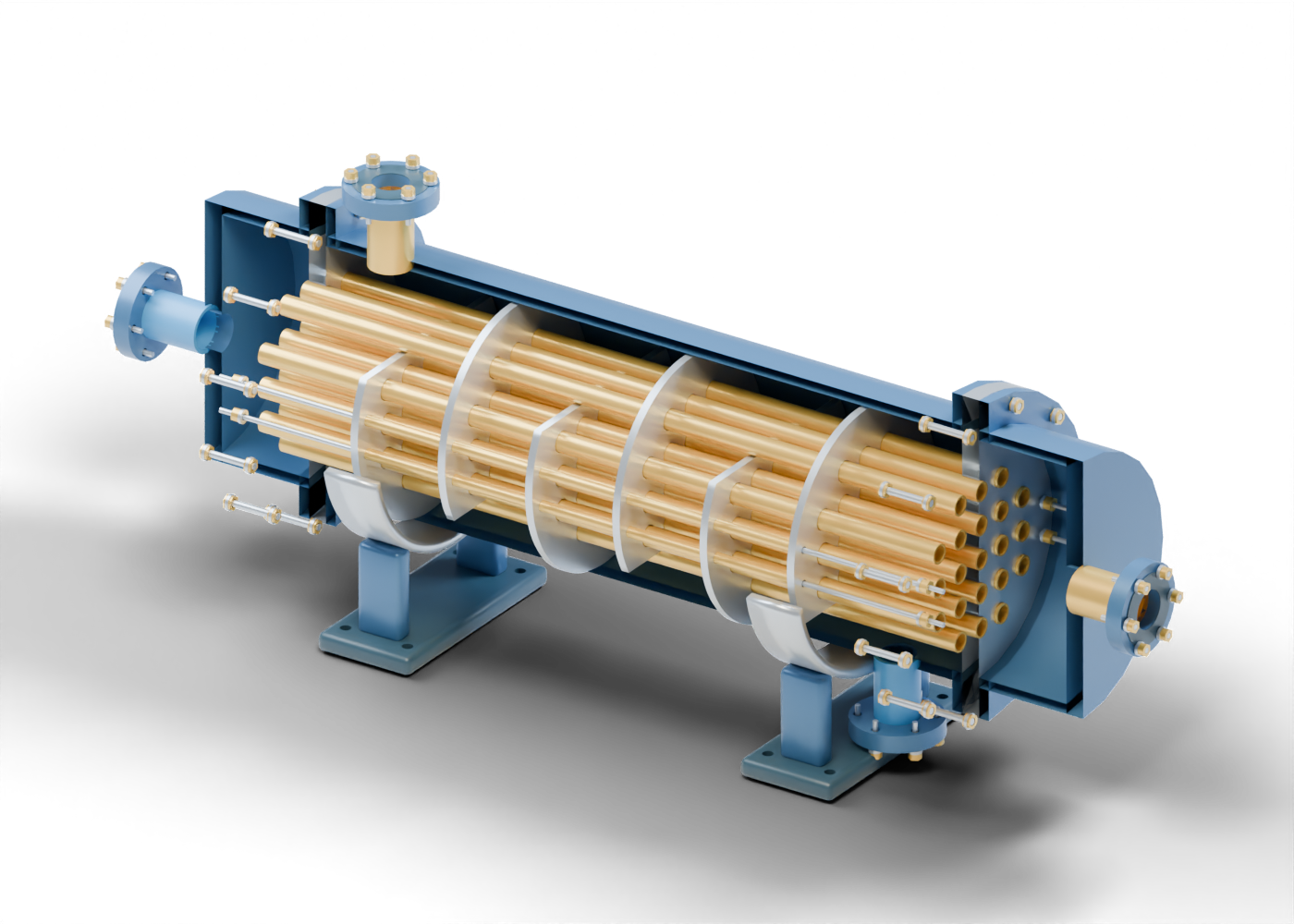
Start with one gold tube in the cutaway. Its central opening extends through the bundle and both drilled tube sheets. The surrounding shell encloses a different space outside those tubes. Seeing both regions helps a reader distinguish a tube-side connection from a shell-side connection in an equipment description.
Our original model has 21 straight hollow tubes and 294 named mesh instances, including repeated hardware. Two axial connections lead into separate end channels; two radial connections enter the shell region. The channels have no pass partitions. Eight guided studies focus on a tube, tube sheet, baffle, tie rod, spacer, channel, shell connection and gasket marker.
This is an invented teaching arrangement. No hot or cold stream, fluid composition, flow direction or pressure difference is assigned. The static view lets readers trace spaces and component boundaries without suggesting a measured process result.
2. Read the tube sheets and channels
Two flat drilled plates lie at the bundle ends. The tubes pass through their individual openings. The tube ends open into the separate end channels beyond the plates, while the shell region lies between them. The original geometry also separates the joint flanges, gasket markers, smooth studs, washers and bored hexagonal nut markers.
The visual gap around a tube is not a specified manufacturing fit. There is no modelled weld, expanded tube joint, tested leak barrier or pressure-qualified attachment. Following a bore through this assembly therefore establishes an opening in the geometry, not a sealed separation between actual process streams.
Likewise, two tube sheets and straight tubes do not establish how a real exchanger accommodates thermal expansion. This concept supplies no qualified floating head, expansion joint or tube-to-sheet attachment system. Those details require the identified product's drawings and design evidence.
3. Inspect the alternating baffles
Six separate segmental baffles sit inside the shell. Each has tube openings, tie-rod holes and a cut-away segment. The open segment alternates between the top and bottom across the bundle. In the 3D lesson, reveal the enclosure and focus on the first baffle to distinguish its retained plate from its open window.
Four smooth tie rods run along the bundle, with 20 hollow spacer sleeves between neighboring baffle faces. These separately selectable pieces make the plate spacing visible. The model does not specify threads, tightening, support loads or an assembly sequence.
The Spirax Sarco learning reference describes tubes inside a shell, tube sheets separating fluid regions, and baffles that support tubes and guide shell-side flow. These basic terms help read the cutaway. Our alternating windows do not calculate a velocity field, pressure loss, bypass, fouling or heat-transfer coefficient.
4. Compare the component boundaries
Use these rows to locate parts in our original model. They describe what the visualization depicts, rather than the qualification of a real installation.
| Part or region | What to inspect in the cutaway | Evidence needed for a real equipment claim |
|---|---|---|
| Hollow tube | A separate bore and surrounding wall through the bundle | Material, wall specification, allowable duty and tube condition |
| Tube sheet | A drilled plate around the individual tube ends | Attachment details, pressure-boundary design and applicable test records |
| End channel | Space beyond the tube ends with an axial connection | Actual pass arrangement, joints and product drawings |
| Segmental baffle | Retained plate and alternating open window around the bundle | Support, clearances and documented thermal/hydraulic design |
| Tie rod and spacer | Separate rod and sleeve between baffle faces | Retention, support loads and assembly details |
| Joint and saddle | Individually named gasket/hardware markers and lower supports | Joint qualification, support/expansion arrangement and foundation evidence |
Read the air-cooled heat-exchanger lesson to compare a finned tube bank and fan arrangement with this enclosing shell. Read the gas-compression train lesson to see how separate equipment is represented in a larger conceptual scene. A component's role in a drawing does not identify a real facility's service.
5. Ask what an upgrade actually demonstrates
When a news report describes an exchanger replacement or efficiency improvement, identify the original and replacement equipment and the reported result. A planned upgrade, manufacturer rating and measured plant outcome are different evidence. A detailed render cannot supply any of those records.
Ask whether the claim identifies the service, operating conditions and measurement period. Which evidence supports the thermal duty or pressure loss? Does a statement concern more capacity, lower energy use, fouling behavior, availability or another result? Is there a documented baseline? The component view helps readers ask precise questions; it contains no field measurements or savings estimate.
6. Explore the original model and source context
Open the shell-and-tube exchanger and air-cooled exchanger to compare our two inspectable concepts. These links are labelled 3D models. Focus and isolation help distinguish a single part; section and separation change its presentation, not its engineering properties.
The Spirax Sarco steam-consumption tutorial was read September 27, 2026. It includes steam-heating, U-tube and pass-partition examples. Our straight-tube, unpartitioned-channel model does not reproduce those examples or inherit their service assumptions or calculations. No source diagram, photograph, equation, product dimension or rating was imported.
Visible openings and retained material do not qualify contact, sealing, thermal expansion, vibration, pressure loss, manufacture or equipment service. This reading supplies no sizing, selection, installation, operating or maintenance procedure.