Distinguish the three equipment jobs
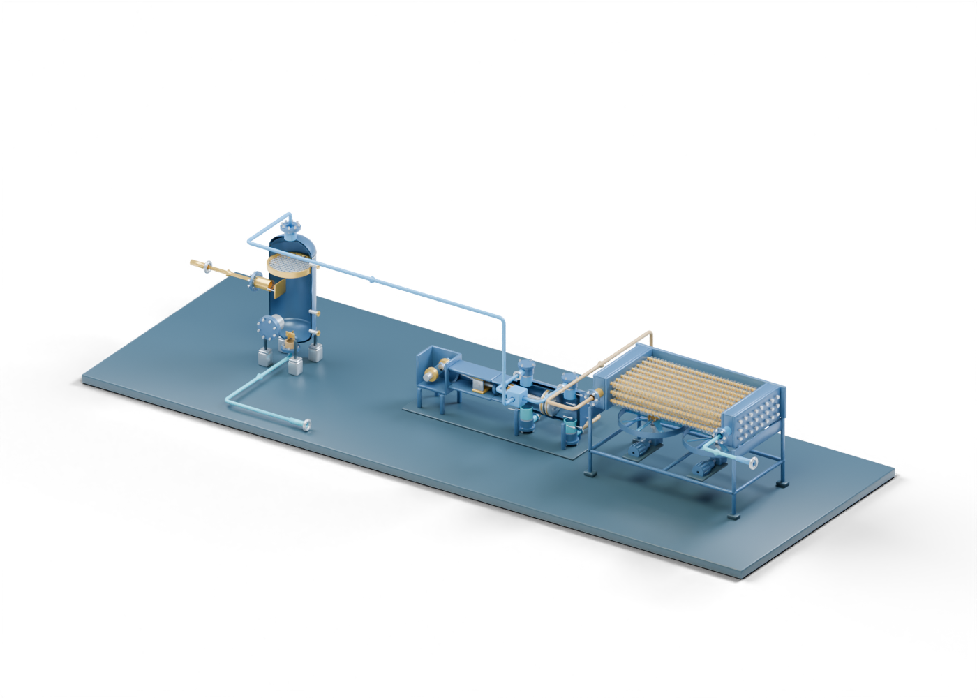
Read the scene from left to right: an inlet gas–liquid separator, a reciprocating compressor and an air-cooled exchanger in an aftercooling role. These names describe different jobs. Removing liquid, raising gas pressure and cooling gas are separate questions; the presence of one component does not answer the other two.
SLB defines a compressor by its pressure-raising role. Its public 2017 scrubber-paper abstract describes liquid removal ahead of equipment including compressors. Those sources support the general vocabulary. Our vessel dimensions, parts and placement are original teaching choices, with no removal efficiency or matched compressor duty. SLB: compressor. SLB: public scrubber abstract, published January 1, 2017.
| Scene region | Relationship to follow | Evidence for an actual installation |
|---|---|---|
| Inlet separator | Incoming mixture becomes separate gas and total-liquid paths | Actual fluid conditions and measured liquid carryover |
| Compressor | Two suction relationships lead into a static cylinder concept; two discharge relationships leave it | Actual pressure, flow, drive power and operating boundary |
| Air-cooled aftercooler | Discharge gas reaches a separate tube, fin and fan assembly | Inlet/outlet conditions, ambient conditions and measured cooling result |
| Total-liquid boundary | The lower separator path ends outside the scene | Identified liquid-handling equipment and its documented scope |
| Further gas-handling boundary | The illustrated path ends after cooling | Actual downstream treatment, measurement and product-quality evidence |
Follow both compressor ends and the liquid path
The original double-acting compressor concept has separate crank-end and head-end suction necks and separate discharge necks. The connected scene shows all four relationships. Two small open junction blocks make the branching legible; they are abstract markers rather than fabricated manifolds or pulsation bottles.
The lower separator outlet takes a different path to an external total-liquid boundary. It does not divide oil from water in this two-phase concept. The upper gas path reaches the suction branches. Focus the equipment groups to keep these relationships separate before selecting individual parts.
Eight graph nodes and nine declared relationships organize the scene. Its 1,537 named mesh instances include the three reused equipment models, repeated fins, lattice members, hardware and new route markers. They do not represent 1,537 distinct products. The connected layout adds context to the detailed parts; it adds no real operating state.
Keep pressure evidence separate from visible motion
The compressor's crank, connecting rod, crosshead, piston rod, packing, piston and valve stacks remain individually selectable. The standalone model has 196 named component instances and guided studies for those regions. It depicts one static geometric pose, without a pressure cycle or a complete drive package.
For a reported compression upgrade, identify the comparison: which equipment, which inlet and discharge boundaries, what observation period and what source for the numbers? A rated capacity, a proposed target and an observed operating result describe different evidence. This illustration provides none of those figures.
The same distinction applies to emissions or efficiency claims. Ask what equipment and activities the reported measurement includes. A cutaway does not supply fuel use, electrical consumption, emissions, throughput or a before-and-after comparison.
Read aftercooling as a separate role
The aftercooler glossary in National Grid's July 2017 Transmission Planning Code describes cooling gas after compression. The document is hosted by National Gas and describes a UK network context. We use that term for the component role, without importing its network limits or treating it as a current Alberta requirement. National Grid: Transmission Planning Code, Appendix G glossary.
Our existing air-cooler concept retains 24 hollow tubes, separate headers, external ring fins and two lower fan bays. The connected scene reuses those original parts. Static route colors identify the relationship before and after the exchanger; they are not calculated temperatures or a simulation of cooling.
The gas path stops at a further-handling boundary. Downstream liquid removal, treatment, dehydration, measurement and export are outside this lesson. The scene supplies no dryness result, carryover result or sales-gas specification. Continue with our air-cooler lesson and glycol-contacting lesson to distinguish the component roles.
Match an Alberta headline to the actual facility
The AER facilities catalogue lists ST50A by gas-plant reporting facility ID and ST50B by facility licence. It also points readers to public facility information and other production-data resources. Those identity references can help distinguish similarly named facilities when reading an Alberta story. AER: facilities products catalogue.
Record the facility identifier, source document and relevant reporting period alongside a claim. Then identify the event: an announcement, an application, construction, startup or a measured operating result. A facility-list entry alone does not establish the claimed upgrade result, and this original scene depicts no listed plant.
The catalogue page we checked on September 27, 2026 states that it was generated on August 27, 2026. We have not imported an individual facility dataset into this lesson or verified a plant-specific operating claim. The links offer reading context, without reproducing source art, drawings or a surveyed layout.
Open the connected scene and the detailed equipment
Start with the connected compression scene. Its original poster and complete reference appear first; choose the labelled 5.9 MB load when you want the detailed interactive assembly. Six path controls distinguish incoming, suction, discharge, after-cooling and total-liquid relationships, with an all-paths reset. Eight guided studies lead to individual parts.
For a closer view, open the vertical gas–liquid separator, reciprocating compressor or air-cooled exchanger. Our compressor reading lesson explains its internal regions in more detail.
The intact models precede the poster-only presentation cuts. The illustrated openings and part relationships do not establish full collision clearance, engineering suitability or a complete plant. This lesson supplies informal reading feedback, without equipment selection, sizing, operating or maintenance instructions.