Start with the changing chamber
A gas-compression headline can describe a machine, a package or a larger station. A reciprocating compressor provides one useful mechanical example: a piston moves back and forth inside a cylinder, changing the working-chamber volume. Suction and discharge valves provide the entry and exit relationships. The European Forum for Reciprocating Compressors explains this positive-displacement principle and distinguishes a cylinder working on one side of its piston from a double-acting arrangement. EFRC: reciprocating-compressor principles.
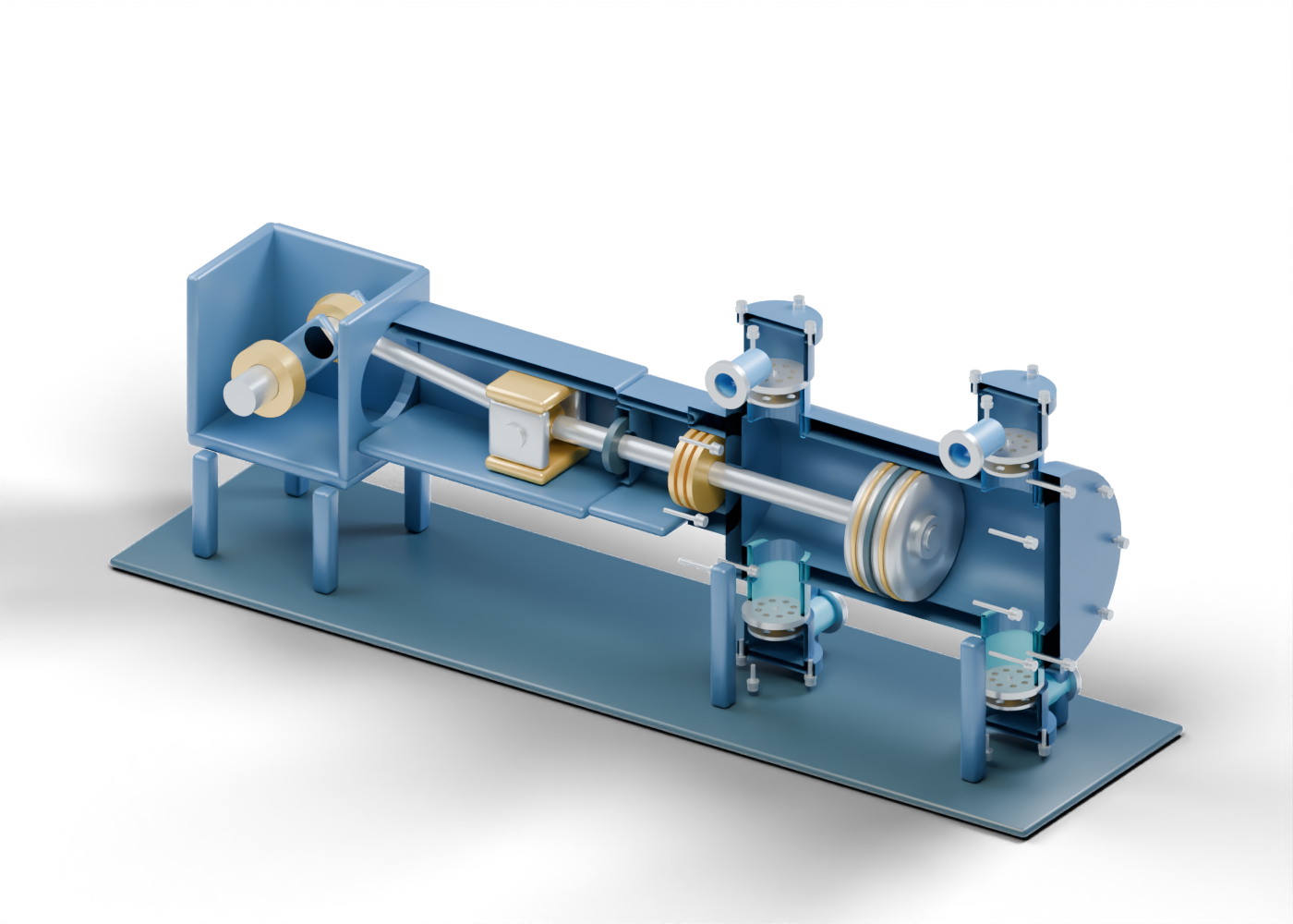
Our original single-cylinder illustration places valve markers near both ends of the cylinder. It is a static teaching concept, with no calculated compression cycle or pressure-responsive valve events. It does not identify a compressor at a company or facility mentioned in the news.
Follow the mechanical connection
Read the picture from left to right. Separate main-journal markers share an axis inside the crankcase region. An offset crank pin sits between two web markers. The larger connecting-rod eye surrounds that pin; the smaller eye surrounds a crosshead pin. A separate smooth piston rod extends from the crosshead region toward the piston.
Ariel's general frame overview identifies crankshaft, connecting-rod, crosshead and guide groups. Those component roles support the vocabulary here, rather than our proportions or a manufacturer-equivalent assembly. Ariel: compressor frame components.
The cutaway removes selected walls and near-half surfaces to make these relationships visible. It is a presentation view, not equipment opened for work. The model has 196 named component instances, including repeated hardware. Its support frame, shoes and bearings have no verified load, fit, travel or lubrication result.
Separate the rod boundary from the piston
The packing markers sit around the smooth rod near the crank-end head. Farther along the same rod, the piston occupies the hollow cylinder. Its two narrow grooves contain separate split-ring markers; a wider central groove holds a rider-band marker. These locations are visibly different in the original model.
Ariel's cylinder overview distinguishes the piston rod, piston, packing, end closures and suction/discharge valve groups. It is a general component reference, not approval of this simplified geometry. Ariel: compressor cylinder components.
| Illustrated group | Relationship to recognize | Evidence still needed for a real machine |
|---|---|---|
| Crank and connecting rod | Offset pin and two rod-eye regions | Actual geometry, bearings and cyclic loads |
| Crosshead and guides | Separate pin, cheeks and guide-shoe markers | Travel, running fit and support requirements |
| Rod packing | A boundary around the rod near the head | Qualified packing, sealing and vent arrangements |
| Piston rings and rider band | Separate markers in piston grooves | Materials, clearances, wear and performance |
| Suction and discharge stacks | Distinct inlet/outlet valve relationships | Actual valve design, events and gas conditions |
The illustration supplies none of the engineering evidence in the final column. Its colours distinguish parts, without an industry colour standard or material specification.
Look inside a valve stack
Each of the four simplified stacks contains a fixed seat with eight geometric holes, a separate annular plate, a perforated guard, a centre pin and a closed coil mesh. Hollow pockets connect toward the cylinder through actual wall openings. Separate side necks mark inlet or outlet boundaries; they do not form a complete common manifold.
In this invented static arrangement, the suction plate lies on the cylinder side of its seat and the discharge plate lies on the outer-pocket side. These relationships help readers compare the stacks. No spring rate, pressure difference, automatic opening, measured lift, flow or leakage is calculated. The cover, flange, smooth studs, washers and bored nut markers also establish no rated pressure joint or retention.
Ask what the project announcement covers
When a report names a compressor addition or capacity increase, identify the equipment boundary first. Does it concern one cylinder, the complete driven machine, a package with associated systems or a larger station? Then check what the number measures, its units and conditions, and whether it is a design target or an observed result.
Our picture omits a complete driver, manifold, cooling, lubrication, gas treatment, ventilation, control and protection system. A larger component count or detailed render cannot establish throughput, efficiency, emissions or reliability. This guide gives a reader vocabulary for following the evidence. It provides no equipment-selection, operating or maintenance procedure.
Explore the 3D component studies
The compressor 3D model has ten guided studies, selectable parts, isolation and section views. Compare it with the downhole rod-pump 3D model to distinguish the compressor's plate-valve markers from a separate plunger and ball-valve concept. These independent prototypes have invented dimensions and are not interchangeable equipment or one matched installation.
For another boundary comparison, read our mechanical face-seal explainer. A rotating shaft-seal concept and the packing markers around this piston rod describe different component relationships; neither illustration qualifies a complete sealing system.