Find the boundary around the shaft
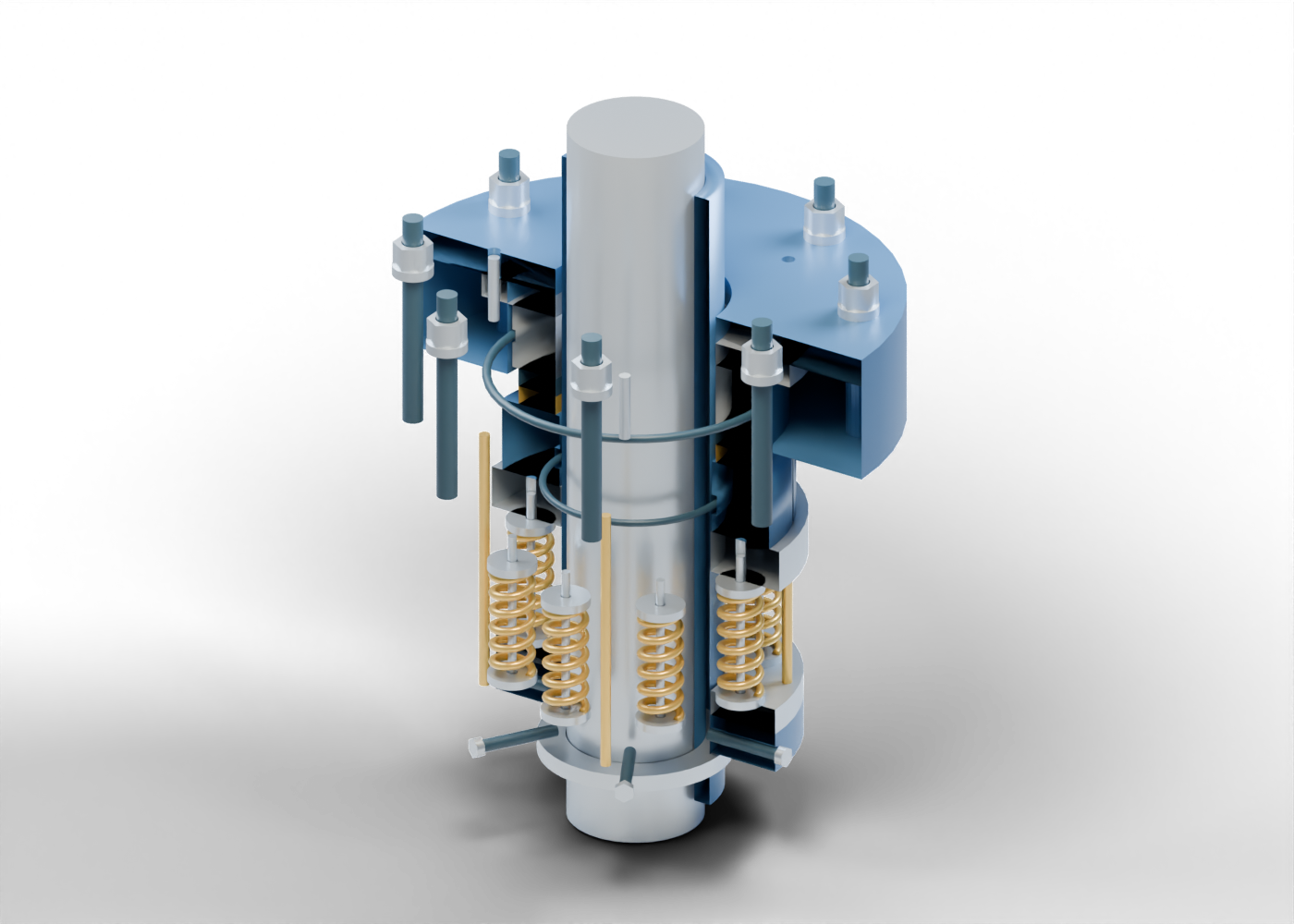
A pump-reliability headline may mention seals without identifying the boundary involved. A mechanical face seal addresses the region where a rotating shaft passes through a stationary housing. Its primary interface lies between a rotating ring and a stationary ring. Secondary seals occupy other component boundaries, and axial loading helps maintain the face relationship. A very thin lubricating film belongs to the physical explanation; a large visual gap is not a measurement of that film. EagleBurgmann: basic mechanical-seal elements.
The original cutaway above is a static teaching concept. It distinguishes those relationships using invented geometry. It does not reproduce a manufacturer seal, identify a pump at a named plant or demonstrate leakage performance.
Read the cutaway from the centre outward
The smooth central shaft passes through a separate hollow sleeve. Around the sleeve, a gold annular face meets a dark stationary face in the full model's neutral pose. Selected near-half surfaces are removed in the picture so the rings and supports can be seen. This is a presentation view, not equipment opened for work.
The full assembly contains 91 named component instances, including repeated hardware. Three separate toroidal markers identify secondary-seal regions: inside the sleeve, within the rotating carrier and around the stationary support. Their supporting recesses are geometric features. Neither the picture nor those recesses establish an elastomer material, squeeze, installation fit or pressure rating.
| Illustrated group | Relationship to recognize | What the picture does not establish |
|---|---|---|
| Rotating and stationary faces | Two annular surfaces at the primary interface | Film thickness, wear or measured leakage |
| Secondary-seal markers | Separate boundaries at the sleeve and supports | Material compatibility or qualified compression |
| Coils, guides and drive-side parts | Distinct loading and drive-side component roles | Preload, torque capacity or axial response |
| Gland, studs, washers and nuts | Enclosure and attachment relationship | A rated pressure joint or approved retention |
Distinguish a spring from a performance result
Eight separate six-turn coil meshes sit around the shaft in this concept, with individual guide pins and seat markers. A bored collar carries six smooth radial screw markers; four separate axial drive-pin markers extend toward the rotating carrier. These parts help a reader identify where component roles differ from the two face surfaces.
Nothing in this static model moves or calculates a force. Its springs have no qualified rate, preload or fatigue life. The aligned faces have no simulated microscopic film, thermal distortion, pressure response or leakage. Colours distinguish the parts and provide no material specification or industry colour standard.
Put the seal back into the pump context
A seal assembly is only one part of the wider pump installation. John Crane describes mechanical pump seals as a rotating/stationary face relationship and distinguishes seal types and associated support arrangements. That overview supports the general concept, not our invented dimensions or a specific installation. John Crane: mechanical pump seals.
Our teaching assembly omits the complete pump chamber, flushing/support system, dual-seal arrangements, thread forms and moving axial compliance. It is independently proportioned from the atlas pump. Comparing the two models therefore does not establish a compatible cartridge, interchangeable parts or a qualified installation. This guide supplies no equipment-selection, operating or maintenance procedure.
Ask what a reliability headline measures
When a story describes a seal upgrade or reliability improvement, look for the equipment and boundary being discussed. Then distinguish a design objective from a measured result. Does the report identify the operating conditions and observation period? Does it explain what was measured, how the comparison was made and whether the change concerns the seal, its support system or the wider pump?
A component count, attractive render or category label cannot answer those questions. The illustration gives a reader a vocabulary for following the evidence; it makes no claim about emissions, service life, safe operation or field performance at a facility mentioned in the news.
Explore the 3D component studies
The mechanical-seal 3D model contains nine guided component studies, selectable parts, isolation and section views. Compare it with the pump 3D model. These are original educational models with no manufacturer endorsement. The two assemblies are not dimensionally matched.
For another component comparison, read our control, isolation and check-valve explainer. Its distinction between a component, actuator and wider system also helps frame questions about a seal reliability announcement.