Distinguish water vapour from free liquid
An inlet separator and a gas dehydrator address different questions. Separating an existing liquid phase is not evidence that water vapour has been removed from the gas. Our three-phase separation guide introduces that upstream vocabulary; the two illustrations are independent concepts rather than one matched installation.
The US EPA describes glycol dehydration as water removal from natural gas and identifies triethylene glycol, or TEG, as a commonly used liquid desiccant. Its explanation also connects water in gas with possible ice or hydrate blockage under particular conditions. That general context does not specify a result for this invented tower. EPA: glycol dehydrators.
SLB's glossary identifies a glycol absorber as the vessel where wet gas and glycol contact each other across trays. This supports the word contactor here; it does not supply our geometry. SLB: glycol absorber.
Read the tower's boundary connections
SLB's system overview describes wet gas entering near the bottom, moving upward, and leaving at the top, while glycol enters above and moves downward through contacting internals. It also distinguishes tray arrangements from packing. Our model chooses four simplified tray levels rather than claiming that every contactor has this arrangement. SLB: glycol dehydration systems.
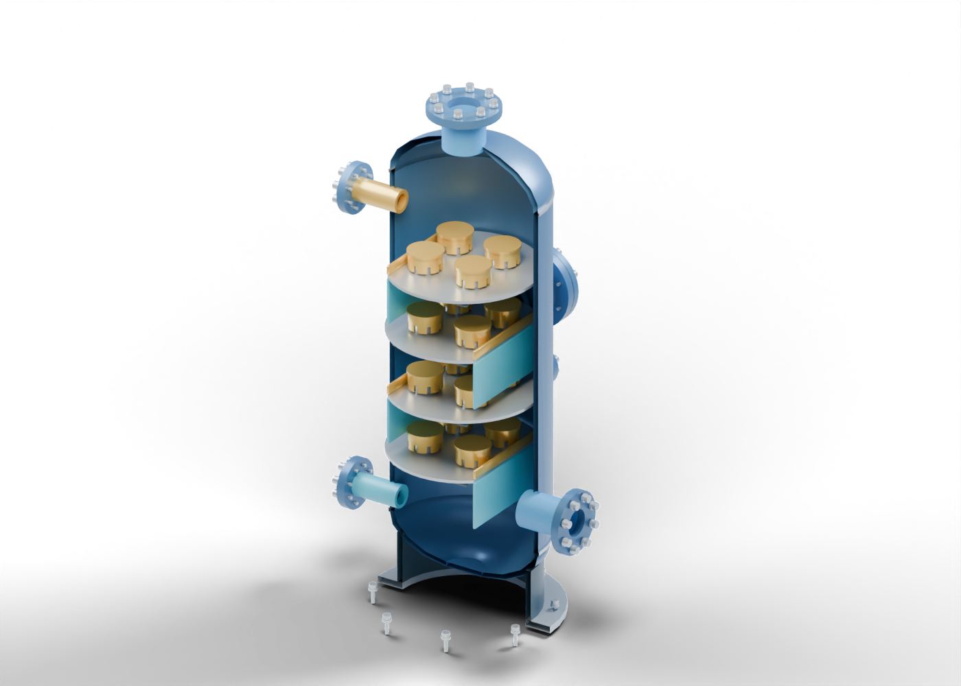
The original model contains 258 named component instances, including repeated caps and fasteners. A lower gas-inlet neck, upper gas-outlet neck and separate lean- and rich-glycol connection markers establish labelled boundaries. They do not simulate circulation, bubbles, contact time or water transfer. The word dry in an outlet label identifies the intended role, not measured water content.
Separate tray, riser, skirt and lid
Each of our four decks carries four cap assemblies. A cap is split into a hollow riser, a hollow skirt and a solid lid. Eight actual lower-edge slots in each skirt make its shape distinguishable from a plain closed cylinder. The presentation cutaway removes selected enclosure surfaces so those pieces can be seen.
An alternating side opening is cut into each deck. Separate weir and downcomer-wall markers distinguish the side region from the cap region. This static geometry establishes no liquid seal, gas-bypass prevention, liquid level, tray hydraulics or removal efficiency.
| Model element | What the illustration shows | What remains unproven |
|---|---|---|
| Tray deck | Four repeated levels with cap and side openings | Required tray count, spacing or performance |
| Riser | A separate hollow passage through a deck | Gas distribution or pressure drop |
| Slotted skirt and lid | Separate parts with open lower-edge slots | Bubbles, contact efficiency or materials |
| Weir and downcomer markers | A distinct side region on alternating decks | Liquid level, sealing or hydraulic behaviour |
| Gas and glycol necks | Separate labelled vessel boundaries | Flow rate, composition or rated joints |
Look for the wider glycol circuit
SLB's overview describes water-rich glycol leaving the tower for reconcentration, with filtering and heating before glycol returns. A contactor image therefore represents only part of that process. Neither the pictured outlet nor the support skirt adds those external systems to our model.
This cutaway contains no complete regeneration equipment, circulation pump, inlet separator, filters, heating/cooling arrangement, mist-removal stage, vent destination, controls or protective system. A detailed vessel image cannot stand in for those missing boundaries. Our separate facility concept also does not contain this contactor or a complete dehydration train.
Keep emissions claims tied to evidence
EPA's example discusses absorbed methane and other compounds, regeneration emissions, and the additional gas associated with a gas-assisted circulation pump. It illustrates why the wider circuit matters. It is a US programme explanation rather than a Canadian compliance finding or a universal description of every installation.
A claim of reduced emissions needs a named system boundary, comparison basis, observation period and supporting method. Our static model calculates none of them. It supplies no methane quantity, vent measurement, recovery result or proof that a particular facility complies with a requirement. No diagram or measurements from the source have been reproduced.
Read the claim, then explore the parts
When a headline describes a dehydration upgrade, identify whether it concerns the tower, regeneration circuit, pump arrangement or whole facility. Then distinguish an announced target from a documented result. Look for the actual equipment and operating context behind any reported outlet quality or emissions change.
The contactor 3D model provides eight guided studies, selectable parts, isolation and section views. Compare it with the separator 3D model to distinguish bulk phase separation from gas-contacting vocabulary. These original prototypes have invented proportions and are not interchangeable equipment or one surveyed plant.
The illustration is static and contains no process, pressure, capacity, dewpoint or emissions calculation. This lesson provides no sizing, selection, operating or maintenance procedure.