Start with the process boundary
A processing headline can name equipment without explaining what happens inside it. A three-phase separator is a useful place to start: its role is to separate a mixed well-fluid stream into gas, oil and water groups. The word three identifies those phase groups, not three identical vessels or three finished products. Horizontal, vertical and spherical arrangements exist. SLB: three-phase separator.
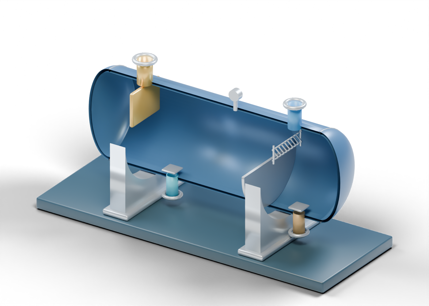
The illustration here is our original horizontal teaching concept. Its proportions, neck positions and internal arrangement are invented. It helps a reader recognize component roles; it cannot identify the equipment at a company mentioned in a news story. A capacity announcement, equipment photograph or model label still needs evidence about the actual installation.
Read the original cutaway
The front half of the enclosure is removed in this render so the internal parts can be seen. The complete model has a cylindrical wall, two dished heads and five geometric wall openings: feed, gas, oil, water and a small instrument tapping. Static phase markers are hidden in the picture. The open view does not depict a vessel opened for work or an installation in service.
Use the picture to identify four relationships:
- Inlet and plate. The gold upper neck leads toward a simple inlet-diverter plate. It marks an incoming boundary and a change of direction in this concept.
- Settling space and weir. The internal plate near the right end marks a collection boundary. A separate compartment sits beyond it in the full model. The plate height is a teaching choice, not a measured level or a sizing result.
- Mist-removal markers and gas neck. The small zigzag elements identify a vane-type concept near the upper outlet. They are sparse markers rather than a complete sealed pack with verified drainage and performance.
- Lower necks and draw-off plates. The two liquid necks occupy different positions relative to the weir. Small plates above them identify conceptual vortex-breaker locations. Their supports and performance are not designed.
The small pressure-indicator marker has no numerical reading. No relief, level/interface control or shutdown system is supplied by this illustration. Model colours distinguish parts; they are not an industry colour standard.
Follow the three outlet groups
Gravity separation provides the basic explanation for the phase arrangement: denser liquid lies below lighter liquid, with gas above the liquid regions in this teaching concept. The actual separation result depends on the fluids and conditions. Our model's phase heights are static markers, with no measured interfaces, retention-time calculation or fluid simulation. SLB: separator.
A gas stream can also carry small liquid droplets. Mist extractors collect those droplets; common concepts include mesh pads and vanes. That role differs from the main liquid collection space. The zigzag markers in our render identify the idea without reproducing a manufacturer's internals or establishing droplet-removal efficiency. SLB: mist extractor.
Distinguish separation, storage and treatment
A separator divides the incoming stream into phase groups. A storage vessel holds an inventory. A route from one to the other identifies a relationship, but a picture of that route does not establish the liquid's specification, quality or approved destination.
Gas processing can also involve dehydration, contaminant removal and recovery or separation of hydrocarbon liquids. The required steps depend on the incoming gas and may occur in different orders or places; a single separator drawing does not establish a complete processing train. EIA describes these general process roles in a United States overview. That source is useful for concepts here, not as proof of a Canadian facility's configuration or requirements. EIA: natural gas processing, delivery and storage.
Questions to ask of a facility headline
When a story announces a new vessel, plant upgrade or throughput target, ask:
- Which equipment or process boundary is changing?
- Does the number describe vessel capacity, a stream rate, a design target or measured production?
- Which fluids, units, period and conditions apply?
- What evidence supports the stated outlet quality or destination?
- Is the image a schematic, an exact product reference, an approved survey or a photograph of that installation?
These are questions for reading a report, not instructions for sizing, operating or maintaining equipment. The original cutaway is educational artwork. It gives no pressure rating, manufacturing specification, hydraulic result or operating procedure.