Separate process flow from cooling air
An air-cooled heat exchanger transfers heat between a process fluid and air. The process fluid stays inside tubes; external fins extend the tube's air-side surface. Hudson's introductory brochure describes the tube bundle, headers, fins, fans and supporting structure. It supplies general vocabulary, not our dimensions or geometry. Hudson Products: the basics of air-cooled heat exchangers.
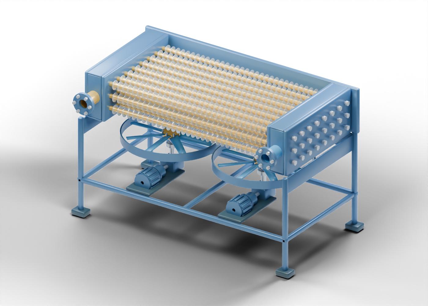
In our original illustration, the blue tubes and gold ring fins belong to one invented assembly. Air is not a second process stream inside those tubes. Compare this boundary with our shell-and-tube model, where the two fluid regions are arranged differently. Neither model contains a heat-transfer calculation.
Follow tubes, fins and headers
The model contains 1,092 named component instances, including repeated fins and hardware. There are 24 hollow tubes in three rows and 768 individual ring-fin instances: 32 on each tube. Repeated instances share some mesh data; these counts do not represent 1,092 different products.
Each tube extends between a pair of header regions. Separate tube sheets contain openings around the tube axes. Closed plug stems and heads occupy distinct openings in the outside plug plates. These features make the regions distinguishable; they do not establish qualified joints, closure seals or a pressure rating.
Hudson describes headers as assemblies that connect the tube ends, with access arrangements and possible partitions for multiple passes. This teaching model uses a single-pass concept with no partition system. Its ring fins illustrate separate tube and fin geometry, not a manufacturer's fin attachment or fabrication method.
Locate the fans and drive parts
Alfa Laval distinguishes forced draft, where a fan pushes air toward the bundle, from induced draft, where a fan draws air through it. For horizontal bundles, its overview places forced-draft fans below and induced-draft fans above. Alfa Laval: air-cooled heat exchangers.
Our invented layout places two eight-blade fans below the bundle. Each bay has separate motor, coupling, shaft, bearing and gear-region markers. They show the relationship between a drive region and a fan region. They do not simulate rotation, gear contact, electrical behaviour, balance or the flow of air.
| Model element | What the illustration shows | What remains unproven |
|---|---|---|
| Hollow process tubes | 24 distinct tube locations between headers | Flow distribution or pressure drop |
| Ring fins | 768 repeated external annular instances | Thermal duty, attachment or fin efficiency |
| Header regions | Tube sheets, plug plates and separate closed plugs | Rated closures, joints or multiple-pass design |
| Fans and drive markers | Two lower bays with separate blades and drive parts | Airflow, power, balance or gear ratio |
| Plenum and support frame | Air-side enclosure and bundle support regions | Qualified clearances, structural loads or site layout |
Read the cutaway as a presentation choice
The interactive model retains the complete geometry. The poster removes the near plenum wall, near bundle frame and fan deck only for visibility. A removed surface in the illustration is not a recommended opening in operating equipment.
The interactive explorer offers eight guided studies, selectable parts, isolation and section views. The model separates tube bores, sheet openings, plugs, ring fins and fan locations without proving thermal duty or pressure loss. The visible shapes and relationships do not qualify thermal, mechanical or pressure performance.
Keep plant and seasonal claims in context
A photograph or a detailed model of one exchanger does not show a complete process plant. This assembly contains no winterization or recirculation system, qualified louvers, control logic, protective system, utility installation or operating procedure. It is not part of a surveyed Alberta facility.
When a news story reports better cooling, identify the actual unit and comparison boundary. Look for inlet and outlet conditions, ambient conditions, observation period and a supporting measurement method. Distinguish an announced target from a measured result. This model provides no temperatures, thermal duty, airflow, pressure drop, power use or water/carbon savings to substantiate such a claim.
Compare the two exchanger concepts
Open the air-cooler 3D model to inspect the fin, header, fan and drive studies. The shell-and-tube 3D model offers a contrasting arrangement. These are independent original concepts, not matched equipment or interchangeable selections.
This lesson gives vocabulary and informal reading feedback; it provides no sizing, selection, operating or maintenance instruction.