1. Read the inlet role
A finger-style slug catcher may sit at the inlet to a gas-processing facility. An AIChE presentation describes separate gas and liquid handling and temporary storage for arriving liquids. That broad role does not tell you how much a particular station can receive.
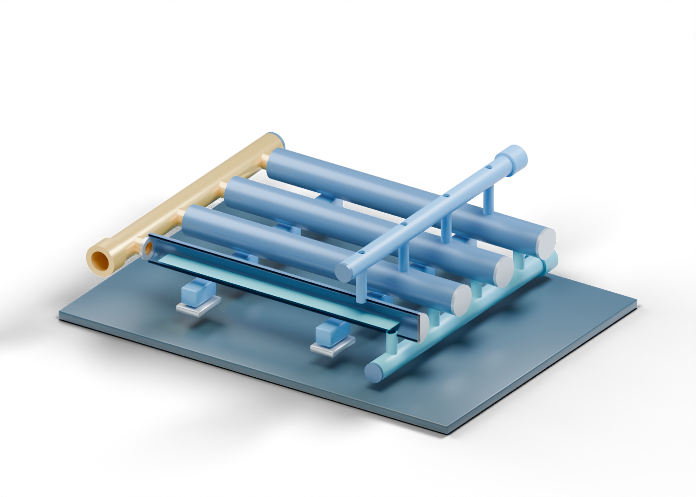
Our original four-finger 3D scene makes three boundaries easy to inspect: a mixed-stream arrival, an upper gas destination and a lower liquid destination. It is a generic learning illustration, not a surveyed Alberta plant or a copied vendor product.
2. Follow the four parallel fingers
The wet-gas inlet header has four open branch locations. Each enters a separately selectable hollow finger. The model uses four fingers so their relationship is legible; their count, length and spacing are invented.
Taylor Forge's discussion of distribution explains why actual inlet and cross-header arrangements need careful engineering. Our aligned openings are geometry checks, not evidence of equal distribution, residence time or an adequate slug-storage volume.
3. Keep gas and liquid destinations separate
An upper gas riser meets the gas collection header. A lower liquid downcomer meets a different liquid header. These are distinct routes in the illustration, consistent with the broad separation role described by Taylor Forge.
The upper opening does not prove dry sales gas. The lower opening does not establish a permitted disposal route. Gas treatment, liquid processing, instrumentation, valves and plant safety systems remain outside this scene.
| 3D element | Helps locate | Does not prove |
|---|---|---|
| Inlet header | Shared arrival boundary | Equal flow into all fingers |
| Four hollow fingers | Parallel hold-up locations | Actual slug capacity |
| Upper risers | Gas-side collection route | Dryness or carryover control |
| Lower downcomers | Liquid-side collection route | Drain-valve behaviour |
| Bored support feet | Separate structural locations | Foundation design or loading |
4. Treat the blue plane as a label
The nearest finger's cutaway poster shows a blue liquid-region marker. In the interactive model, all four fingers retain complete walls; reveal their interiors or use the part list to inspect each marker. The planes are arbitrary and static. They do not simulate a moving slug, gas-liquid interface, stratification or a pigging event.
The separate closed far end helps show that the finger is a collecting location. Its shape does not qualify a pressure boundary.
5. Ask for the real project basis
When a project announcement says a new slug catcher increases inlet capacity, look for the specified incoming liquid case, flow and gas composition, the temporary liquid volume, downstream handling, applicable code and the basis for the claimed change. The illustration cannot supply those values. A finger-style layout can also occupy substantial space, as the AIChE overview notes, so a render alone says little about a real site footprint.
Our separate pigging-vessel lesson helps distinguish pipeline maintenance equipment from inlet liquid collection. The coalescer lesson addresses a different downstream droplet-removal concept. These models are not one matched process train.
6. Explore exact parts
Open the 3D slug catcher, select the mixed arrival, compare the gas and liquid destinations, and inspect one bored foot. The 62 named parts are inspectable teaching geometry. They establish no process capacity or safe operating procedure.