1. Trace the circuit as separate jobs
The absorber and regenerator are different vessels in a wider gas-treating arrangement. A conventional acid-gas-removal flow also gives the rich/lean exchanger, cooler, pump, reboiler and condenser separate roles. NETL's 2013 baseline depicts those roles in Exhibit 3-3; its report concerns an integrated-gasification study and does not document an Alberta gas plant. NETL: conventional acid-gas-removal flow, Exhibit 3-3.
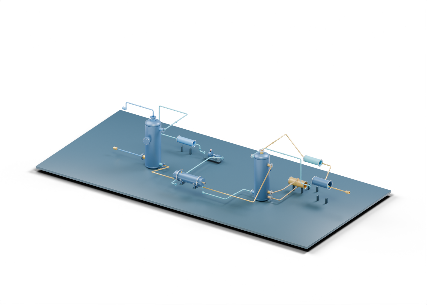
Our original Alberta-blue and prairie-gold 3D teaching scene joins four independently authored detailed models: an absorber, a regenerator, a shell-and-tube exchanger and a centrifugal pump. Four additional envelopes stand for the reboiler, condenser, overhead receiver and lean cooler. The 631 named selectable meshes and fourteen hollow static relationship routes make roles and boundaries easier to inspect. The receiver and the exact arrangement of every line and object are our own illustrative choices, not copied source engineering.
2. Keep gas and solvent paths distinct
The feed-gas boundary points to the absorber. A treated-gas boundary leaves it, while the rich-solvent path leads away from a lower vessel opening toward the exchanger and regenerator. The drawing uses separate colours and selectable paths so a reader can trace these ideas without confusing a gas line with circulating solvent.
Rich solvent is a role label: the model supplies no composition, acid-gas loading, pressure or measured flow. The inlet and outlet positions are invented. The absorber cutaway guide explains what can be seen inside that independently proportioned vessel; this placed reuse does not prove a matched connection.
3. Follow heat and solvent return without assuming a heat balance
The exchanger model illustrates two separated stream-side roles. A line then reaches the regenerator rich-feed boundary. Lower vessel ports mark a reboiler withdrawal and return; the reboiler itself is a simplified exterior envelope. Lean solvent is shown returning via the exchanger, pump and cooler toward the absorber.
The presence of these objects does not establish solvent selection, regeneration efficiency, heat duty, pump head, exchanger rating, cooler performance or actual circulation. Even the order and visual lengths of the routes are a teaching layout, not a piping and instrumentation diagram or operating sequence. The regenerator cutaway guide details its separate openings and internal markers.
4. Read the overhead branch as an open boundary
An overhead line leaves the regenerator for a condenser-shaped envelope and receiver-shaped envelope. A separate static route marks a reflux-return concept; another ends at an acid-gas boundary. The scene does not take that boundary through sulfur recovery, compression, transport, disposal, monitoring or permitting. It establishes neither emissions compliance nor acid-gas composition.
| Scene region | What the model lets you inspect | What remains unverified |
|---|---|---|
| Absorber and two gas boundaries | Separate feed and treated-gas locations | Feed analysis, outlet quality and treating result |
| Rich and lean routes with exchanger | Declared solvent-side relationships | Flow, heat balance, pressure control and matched nozzles |
| Regenerator and reboiler interfaces | Separate rich feed, lower withdrawal and return, lean outlet | Selected internals, duty, steam supply and stripping efficiency |
| Pump and lean cooler | Distinct circulation and cooling roles | Pump curve, cooler rating, solvent temperature and materials |
| Overhead, condenser, receiver and reflux | Separate overhead and return ideas | Condensation duty, reflux ratio, acid-gas destination and permits |
5. Put a project claim against real evidence
A render cannot show whether a proposed plant is built, commissioned or achieving a specified outlet. For a project claim, ask which asset and date it describes, which equipment was actually installed, and which feed and outlet records support the claimed capacity or quality. Engineering and operating evidence would also be needed for solvent chemistry, heat and mass balance, protection and shutdown, corrosion, relief, containment and H2S handling.
This scene is neither a vendor product representation nor a facility survey. The deep source models have independently invented proportions, and the four auxiliary envelopes are deliberately schematic. Colours and arrows are explanatory, not industry-standard piping colours or live measurements.
6. Inspect the original 3D scene
Open the whole amine circuit and use its stream filters to follow one role at a time. Focus the rich-solvent route, regenerator rich-feed opening, reboiler envelope and cooled lean-return route.
Use the separate absorber and regenerator guides to examine their more detailed internal models. No lesson here supplies a safe operating, maintenance, design or equipment-selection procedure.