1. Put the vessel in the treating circuit
An amine gas-treating absorber is one vessel in an acid-gas removal system. In a conventional arrangement, sour gas containing acid-gas components such as hydrogen sulfide or carbon dioxide enters the absorber while lean solvent enters above it. Contact between the streams produces treated gas overhead and rich solvent below. NETL's 2013 cost-and-performance baseline depicts this countercurrent absorber within a larger acid-gas removal circuit. Its diagram supports the general flow relationship, not the dimensions or performance of our illustration. NETL: cost-and-performance baseline, Exhibit 3-3.
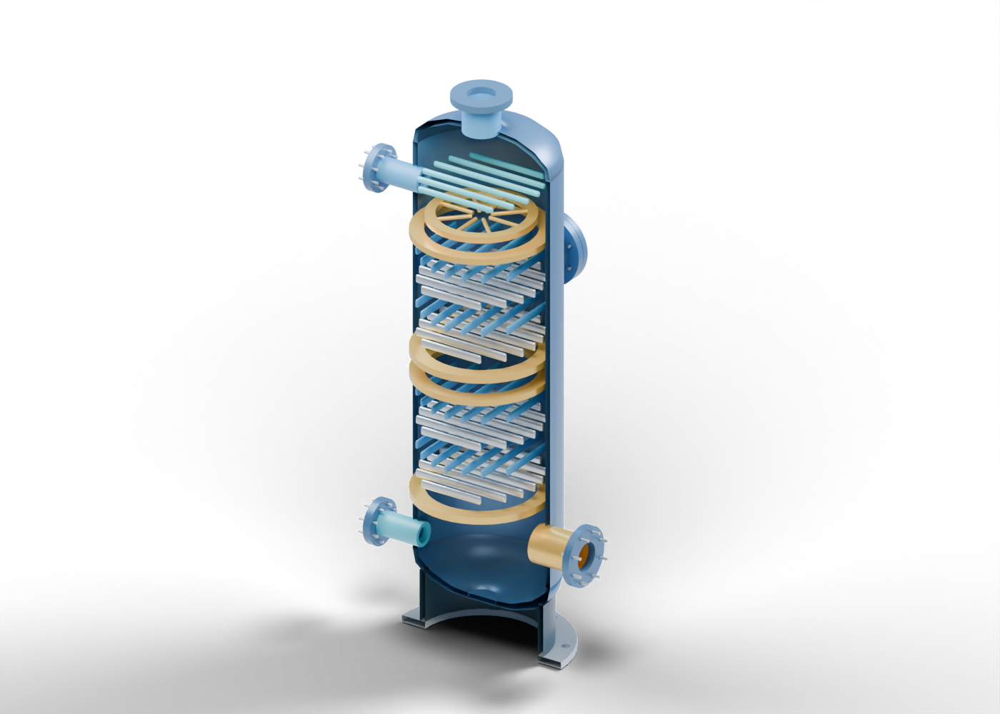
This original 3D teaching model has 125 named mesh components. It uses Alberta blue for the shell and gold for the internal contacting regions. The cutaway is an invented, static educational assembly. It is not a model of a named Alberta plant, a vendor design or a measured treating result.
2. Trace four boundaries in the cutaway
At the lower side, a separate sour-gas inlet neck meets a drilled wall opening. Higher on the vessel, another drilled side-wall passage meets a lean-amine inlet and distributor marker. A top neck identifies the treated-gas outlet. The bottom outlet represents rich solvent leaving this vessel. These visible passages and labels teach the four stream locations; they do not specify flow direction inside every nozzle, pressure, composition, removal target or actual connection size.
The drawing contains a hollow shell and heads, three sampled side-wall bores and a top gas passage. A closed, bored manway marks an access location; it is not an opened vessel or an instruction for entry. A supporting skirt locates the vessel visually without establishing foundation or structural design.
3. Read the internals as locations, not results
Two open lattices made from 28 individual slats each mark lower and upper contacting regions. The upper distributor and an overhead marker make their general roles visible. They are intentionally simplified, invented geometry. A slat in this model is not qualified packing, a tray, a mist eliminator or a vendor product. The cutaway cannot establish wetting, residence time, pressure drop, foaming, entrainment or achieved acid-gas removal.
| Visible region | General role it helps explain | Evidence still needed for a real installation |
|---|---|---|
| Lower sour-gas inlet | Feed-side vessel boundary | Feed composition, rate, pressure and upstream conditioning |
| Upper lean-amine inlet and distributor | Solvent entry and distribution location | Solvent formulation, circulation and actual distributor design |
| Two open contacting markers | Possible locations for gas/liquid contact | Selected internals, hydraulics, mass transfer and inspection records |
| Top treated-gas outlet | Product-side vessel boundary | Measured outlet composition and stated specification |
| Bottom rich-solvent outlet | Return path toward solvent regeneration | Actual piping, equipment and handling arrangement |
4. Follow rich solvent beyond this vessel
An absorber alone does not complete the cycle. NETL's conventional acid-gas removal flow includes rich-solvent handling and a separate stripper or regenerator before lean solvent returns to the absorber. Heat exchange, cooling and pumping belong to the wider process arrangement, with site-specific design and controls. The Union Carbide 1997 conference paper, hosted by NETL, also describes the general distinction between feed gas, lean solvent and rich solvent in an acid-gas removal context; its gasification examples are not a survey of Alberta field installations. Union Carbide conference paper hosted by NETL.
Our model stops at the absorber boundaries. It omits a connected regenerator, acid-gas handling, solvent storage, instrumentation and protection systems. Nothing here shows that a facility removes all contaminants or meets a specified emissions or pipeline-gas limit. Amine gas treating addresses acid gases; glycol dehydration addresses water removal. Those are separate duties even when both appear in a broader gas-processing story.
5. Ask what the project evidence actually says
When a news release mentions a gas-treating plant, ask whether it identifies the feed and its acid-gas composition, the promised outlet target, the status of construction or commissioning, and the source of any reported performance number. A proposed capacity is not a measured removal result. A cutaway, photograph or equipment order does not establish a permitted, operating facility. If a report names a site, check the cited record for the actual asset and location instead of mapping this teaching model onto it.
This explainer provides vocabulary for reading public sources. It makes no service, operating, maintenance or safety recommendation.
6. Inspect exact parts in the 3D atlas
Open the amine absorber for ten guided component studies, selection, isolation and a cutaway view. Follow the sour-gas inlet, lean-solvent distributor, lower contacting marker and treated-gas outlet as exact named parts.
Compare the glycol dehydration guide and gas compression train guide to distinguish treating, drying and compression functions. Their independent illustrations are not a connected or dimensionally matched facility.