1. Follow solvent beyond the absorber
Gas-treating news often names the absorber and leaves the solvent circuit unexplained. In a conventional amine acid-gas-removal arrangement, rich solvent from the absorber goes to a separate stripper or regenerator. A reboiler supplies heat to that wider system; an overhead acid-gas stream leaves toward separate handling, while regenerated lean solvent returns toward the absorber through additional equipment. NETL's 2013 cost-and-performance baseline shows the absorber, stripper, rich/lean exchanger, reboiler, condenser, cooler and pump as distinct roles in its conventional flow diagram. NETL: conventional acid-gas-removal flow, Exhibit 3-3.
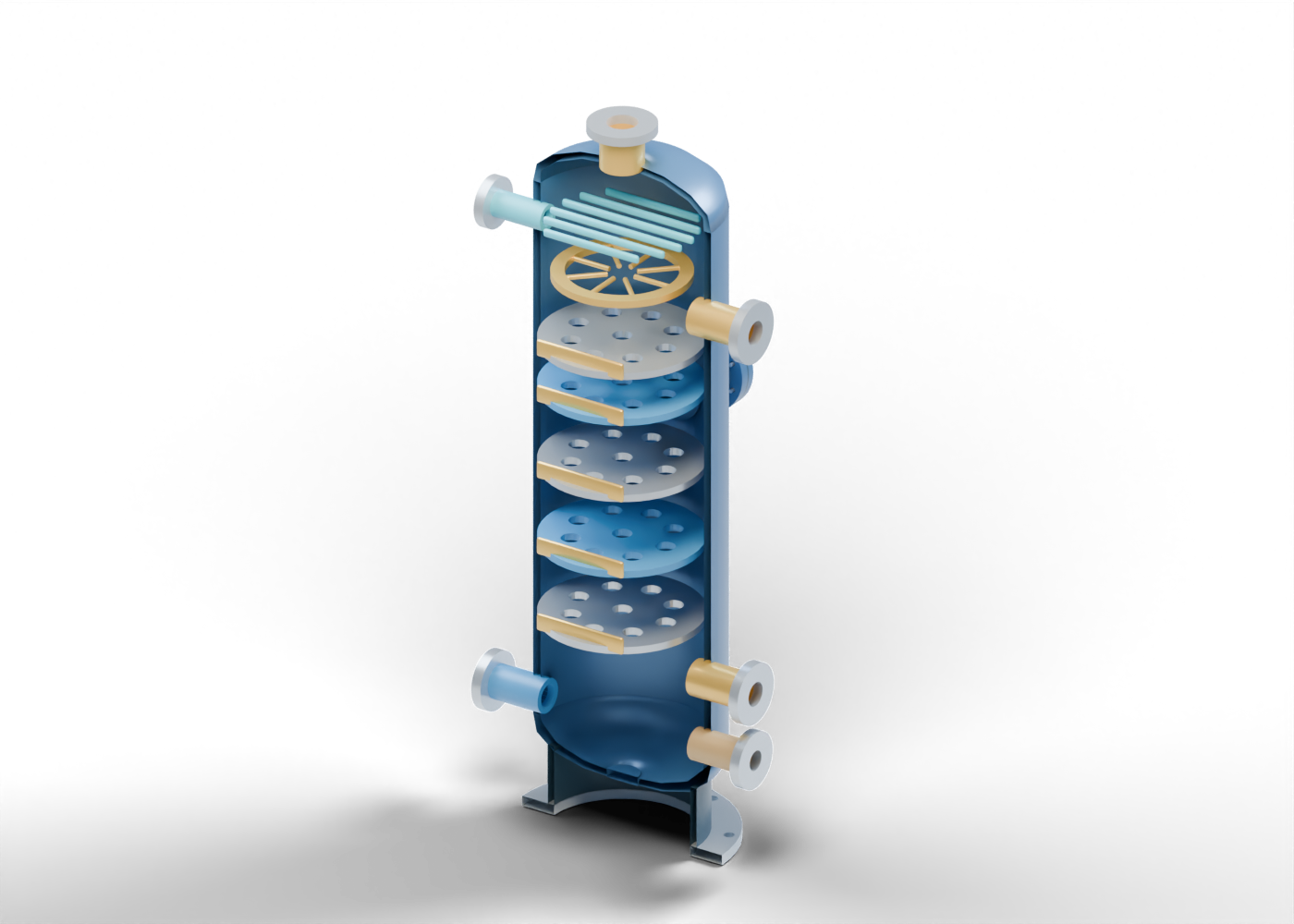
Our original Alberta blue/gold 3D cutaway illustrates one regenerator vessel, with 55 individually named mesh parts. It does not reproduce NETL's diagram or model a named Alberta facility. No temperatures, solvent chemistry, acid-gas removal result or energy demand can be read from its colours or proportions.
2. Read six separate boundaries
The upper rich-solvent feed marks a possible entry from the absorber-side circuit. A second upper neck identifies a reflux-return location. At the top, the open overhead neck marks an acid-gas outlet from this vessel. Lower down, two independent side openings mark reboiler liquid withdrawal and vapor return; a separate opposite-side outlet identifies lean solvent leaving the regenerator. The lower openings are visually separate so a reader can ask what each line does. They are not a piping and instrumentation diagram, verified connections or an operating sequence.
The interactive model has a hollow wall and heads, drilled side-wall passages, a top opening and a closed drilled access boundary. The poster removes a facing half of the enclosure only for explanation. The cover is closed in the complete model; neither the poster nor the viewer suggests a safe vessel-opening method.
3. See the contacting region without inferring performance
Five separate deck-shaped markers sit inside the vessel. Each has nine actual geometric perforations and a visible gap to the wall; a partial gold rim makes their levels easy to distinguish. These are invented visual features. They are not selected trays, downcomers, packing, internals supplied by a vendor or a calculation of vapor-liquid contact. Their count and spacing cannot establish residence time, stripping efficiency, flooding margin or pressure drop.
An upper ring with eight branch markers identifies a possible feed distribution region. Six overhead slats mark a place to discuss entrainment control. Neither feature establishes liquid uniformity, mist-removal efficiency, a reflux ratio or acid-gas quality.
4. Keep the wider circuit outside the vessel
| Model region | General process role to recognize | What the illustration does not prove |
|---|---|---|
| Rich-solvent feed | Return from an absorber-side circuit | Actual feed composition, rate or conditioned pressure |
| Perforated contacting markers | Possible vapor/liquid contact locations | Selected internals or measured stripping performance |
| Reboiler withdrawal and return | Two vessel interfaces to external heating equipment | Reboiler design, duty, steam supply or circulation |
| Overhead acid-gas outlet | Separate gas-side boundary | Composition, sulfur recovery, emissions or permitted destination |
| Lean-solvent outlet | Return path toward reuse | Solvent quality, cooling, pumping or a matched absorber connection |
NETL's broader flow also includes a condenser and rich/lean exchanger. Those items, a reflux receiver, solvent controls, protection and acid-gas handling are not inside this 3D vessel. A heater shown by a boundary label is not a modeled heat source. The companion absorber guide explains the separate gas-treating contact role; the two illustrations are independently proportioned and do not make an integrated, qualified plant.
5. Ask for evidence behind a project claim
When a project announcement says it will regenerate solvent or expand sweetening capacity, check whether it names the operating asset, whether equipment is proposed, installed or commissioned, and which feed and outlet measurements support a stated result. A design target, order or render is different from a measured performance record. Heat duty, solvent circulation, acid-gas handling and permit status need their own cited evidence; none can be supplied by this cutaway.
This article is a source-linked reading aid, not engineering, selection, operating, maintenance or safety instruction.
6. Inspect the 3D model and compare the absorber
Open the amine regenerator for ten guided stops, exact-part selection and a half-section view. Inspect the rich feed, upper contacting marker, reboiler withdrawal and overhead acid-gas boundary.
Then compare the absorber guide and glycol dehydration guide. Absorption, solvent regeneration and water dehydration are distinct functions. These original examples do not specify a connected Alberta installation.