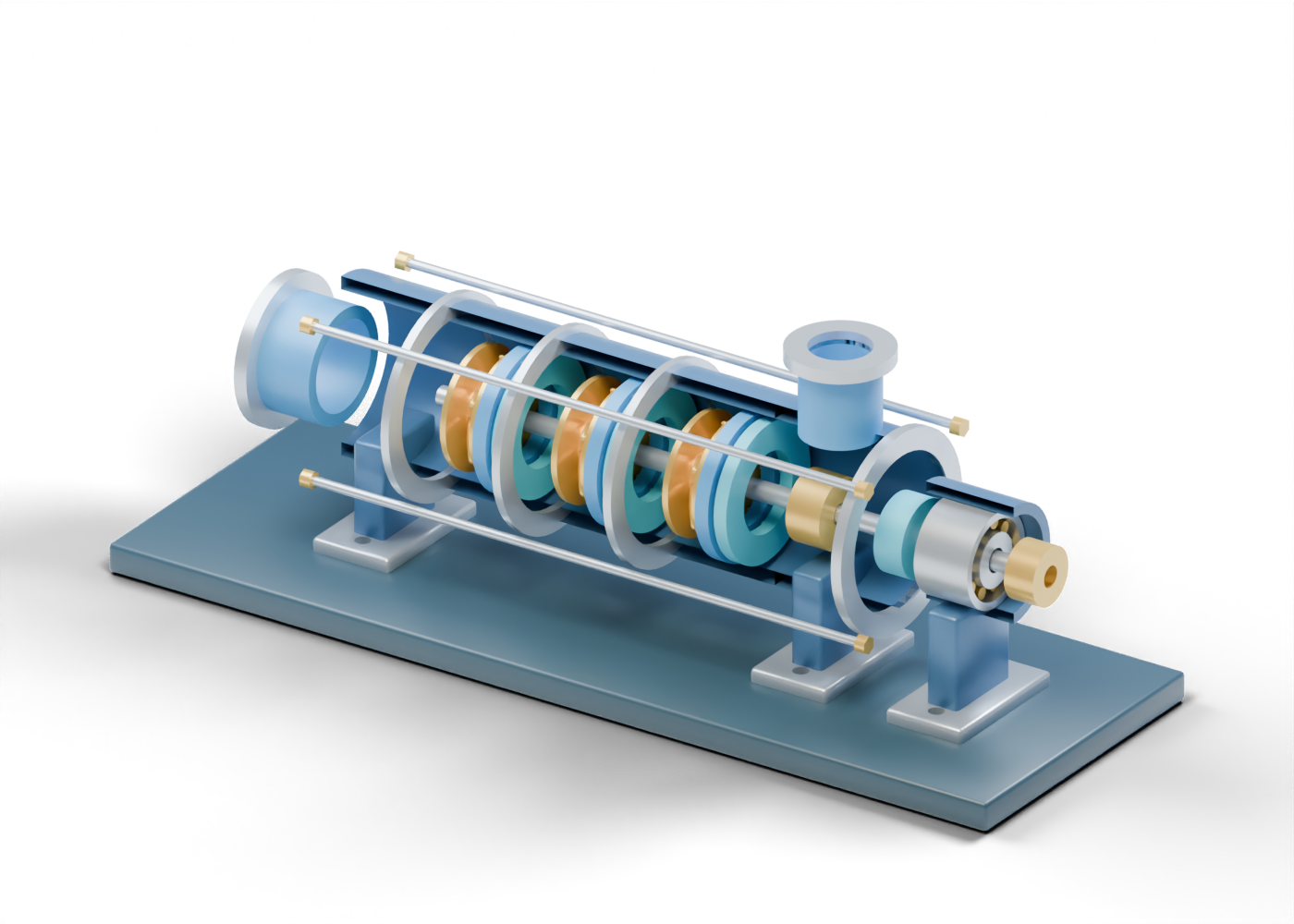
1. Why use several stages?
A multistage centrifugal pump has impellers in series, according to the KSB multistage-pump lexicon. That general arrangement can build more head than one stage at a given speed; an actual duty still depends on the selected pump and system. Compare our single-stage centrifugal-pump lesson with the original three-stage cutaway. The two teaching assemblies have invented, unmatched proportions. Neither supplies a pump curve, flow rate or pressure rating.
2. Read a stage as three distinct component roles
Start at the open axial suction neck and first impeller vane. In KSB's description, a ring-section stage includes an impeller, diffuser and return guide vanes. Our gold vane sits between separate shrouds, while the stationary diffuser vane and blue return guide vane are independently selectable. KSB explains the diffuser's general velocity-to-pressure role and the return guide's inward approach to a following stage.
The second-stage impeller and third-stage diffuser repeat those labels so a reader can compare positions. Their shapes are invented visual fins. The gaps between them have not been checked as a continuous wetted passage, and nothing in the model calculates energy transfer or pressure recovery.
3. Look through the ring-section casing
The first, second and third casings are complete hollow meshes in the interactive model. The article image removes the facing halves only to show the parts. Four external tie-rod locations run across the stage stack. The end casing has an actual upper opening to the hollow discharge neck. KSB names casing, tie bolts and discharge-side components as general elements of ring-section pumps, but our joint rings, rods and flanges carry no pressure or fastening specification.
4. Separate shaft, balance, seal and bearing questions
A common static shaft passes through the three teaching stages. Near the drive end, the balance-drum marker, seal-gland region, bearing roller cue and coupling hub cue identify different questions. KSB's balancing-device reference explains the general need to address rotor axial thrust and notes that a drum arrangement can leave residual thrust for a bearing. Our gold ring is only a location marker: there is no calculated force, balance flow, selected seal or rated bearing.
| What you can inspect | What a real equipment claim still needs |
|---|---|
| Three named stage groups | Selected impellers, passages, curve and duty |
| Complete casing sections and tie rods | Material, joint design, pressure rating and tests |
| Bored discharge location | Actual nozzle, piping and system boundaries |
| Balance and bearing cues | Calculated thrust, selected device and support |
| Seal and coupling locations | Seal plan, driver, alignment and service record |
5. Where might the concept appear?
KSB discusses ring-section multistage pumps for industrial higher-pressure service and describes boiler-feed pumps as multistage radial-flow machines. That is application context, not evidence that this cutaway is a suitable boiler-feed or oilfield pump. The separate electric submersible pump lesson also has three visible impeller/diffuser teaching stages, but represents a different downhole assembly. Our once-through steam-generator lesson is another independent scene, not a plant matched to either pump.
6. Use the model to frame a better question
Open the full 115-part explorer and compare the first-stage impeller, diffuser and return guide. Then ask what measured duty, fluid, selected product, drawings and acceptance records would be needed to support a real performance or safety statement. A clear 3D component map helps identify the question; it is not a fabrication, selection, maintenance or operating instruction.