1. Separate droplets from vapour in the headline
A gas–liquid coalescer addresses liquid droplets carried by gas. Coalescing media collects small droplets, which join into larger drops and drain. Pall distinguishes this role from bulk liquid separation. Parker's instrumentation reference separately describes coalescing elements and adsorption media for vapour removal. These are different claims: a story about liquid aerosol removal does not by itself establish removal of material still in the vapour phase.
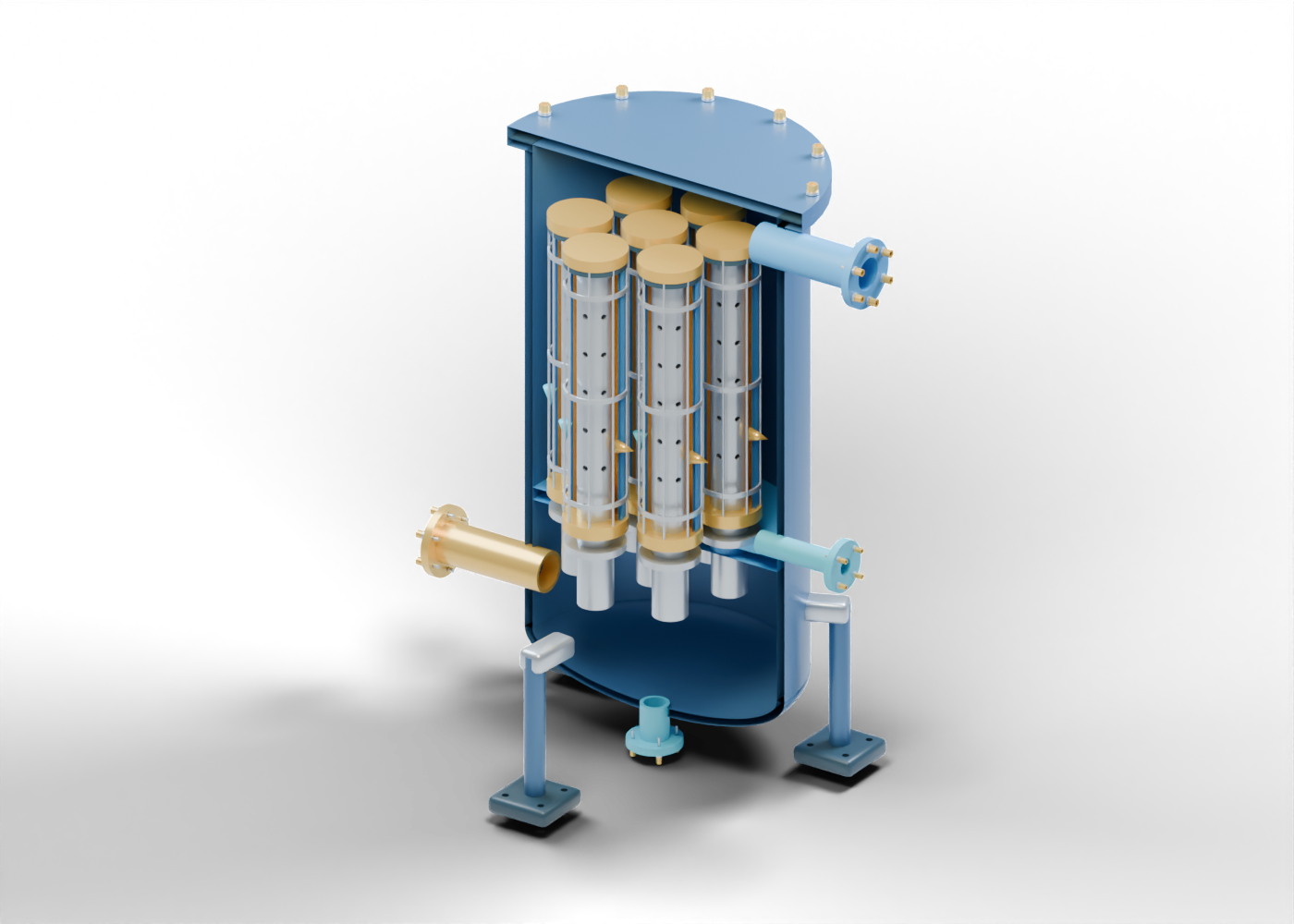
Our original teaching assembly contains seven cartridges and 275 named mesh instances. Its gold and blue shapes identify media and drainage regions, but those meshes are solid envelopes. They contain no real fibres, interconnected pores or droplets. Ten guided studies in the companion atlas let readers inspect the actual hollow cores, boundaries and supports.
The model has invented proportions. It represents neither an identified supplier product nor an Alberta plant installation. Its number of cartridges is a teaching choice, with no selected flow duty or filtration rating.
2. Follow the feed into a cartridge
Start below the horizontal Cartridge tube sheet. The side inlet opens into the lower incoming region. Seven hollow standoffs pass through actual circular holes in the tube sheet and extend into the hollow cartridge cores above it.
Each core has thirty-six radial openings. Those visible holes belong to our coarse support geometry; they are not a media pore-size specification. A separate cap closes the illustrated axial passage at the top. Mounting collars, end rings and seal-location markers remain separate named parts.
Parker's reference includes coalescing media with an inside-to-outside relationship. Our fixed radial arrows illustrate that vocabulary. They do not calculate gas velocity, pressure loss or a particle path. Visible feed axes and closed caps locate parts without proving sealing contact or preventing real bypass leakage.
3. Keep collection regions distinct
The upper-side liquid neck sits above the tube sheet. A different neck passes through the curved lower head below it. The original assembly stops at these two separate boundaries: there is no connecting drain line, drain valve, level-control system or downstream liquid-handling destination.
The outer cartridge envelope marks a drainage region beside the media envelope and cage supports. Downward arrows are annotations, not liquid films or manufactured tubes. The drawing provides no liquid level, drainage rate or carryover result.
Two hollow pressure-tap necks locate the lower and upper regions. No sensing element, tubing manifold or differential-pressure instrument joins them. Their positions therefore supply no pressure reading, alarm threshold or cartridge-change rule.
4. Match each component to the evidence it supplies
| Original component | What the teaching assembly shows | What requires separate evidence |
|---|---|---|
| Feed standoff and tube sheet | Seven hollow feeds through actual drilled positions, with retained plate between them | Qualified mounting contact, bypass sealing and selected gas duty |
| Perforated core and closed cap | Thirty-six coarse core openings per cartridge and a closed upper axial boundary | A media pore rating, capture efficiency or real cartridge strength |
| Media and drainage envelopes | Two separately named solid annular visual regions | Fibre construction, connected porosity, droplet capture and liquid drainage |
| Upper and lower liquid necks | Independent hollow boundaries on opposite sides of the tube sheet | Drain controls, actual liquid levels and downstream handling |
| Pressure-tap necks | Two geometric connection regions | A connected instrument, measured differential pressure or change threshold |
| Joints, cage and supports | Separate hardware, gasket-location markers, rails, bands and drilled feet | Threads, preload, sealing contact, material, load and foundation qualification |
The three-phase separation lesson distinguishes bulk gas, oil and water regions. The dry-cyclone lesson instead discusses a gas–solid separation concept. These are independent teaching assemblies, with no matched installation or equipment-selection recommendation.
5. Read a filtration claim with its conditions
A report may describe a supplier specification, a laboratory demonstration, a proposed upgrade or a measured plant result. Keep that distinction attached to the claim. A detailed render does not turn a proposed result into measured performance.
Ask which equipment and element revision the statement concerns. What material was measured, at what location and over which period? Are incoming and outgoing conditions comparable? Does the evidence concern droplet removal, liquid carryover, pressure difference, availability or another outcome? Identify the primary record and whether the result applies to the actual configuration discussed.
Pall identifies laboratory and field evidence, carryover and pressure loss as separate parts of evaluating gas–liquid separation. This lesson supplies no numerical threshold, test protocol, sizing, selection or operating instruction. In particular, a pair of tap locations or a component's appearance cannot establish a removal-efficiency result.
6. Explore the model with its limits visible
Open the gas–liquid coalescer and compare the vertical gas–liquid separator. The coalescer's component search and exact-name links can focus an individual core; Reveal internals changes visibility, while the direction-marker control shows or hides static arrows. These are presentation controls, with no opening or maintenance sequence.
Primary reading checked September 27, 2026: Pall's gas–liquid separation vocabulary and Parker's Instrumentation and Gas Sampling Filters reference, specifically the coalescing and adsorption role descriptions. No publisher or manufacturer endorsement is implied. No source diagram, photo, OEM CAD, product dimensions, grades, fibre recipe or performance table was imported.
The original model provides no porous fluid domain, capture or carryover result, pressure loss, qualified sealing, material, manufacturing or structural result, complete plant, or installation, operating and service procedure.