1. Start with the separation role
A dry cyclone illustrates inertial separation of particles carried in gas. The general gas relationship descends near the enclosure wall and returns upward toward a central outlet, while collected solids have a lower boundary. The EPA describes this arrangement as a cyclone separation concept, with a cylindrical region, cone, gas outlet and dust outlet. The cyclone enclosure itself is not a rotating impeller.
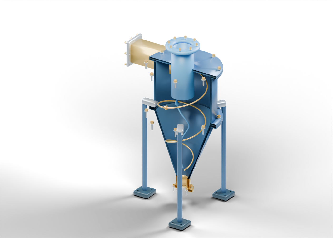
Our original illustration is a 141-instance teaching assembly, with every component separately named. It includes an offset rectangular inlet, a hollow body and cone, a central outlet extension and separate joints and supports. It contains no measured particle distribution, gas quantity or field result. Eight guided studies in the companion atlas help readers inspect those particular shapes.
The word dry distinguishes the role being illustrated here. This is not a gas–liquid vessel or a hydrocyclone model. It does not establish suitable service for a particular Alberta facility, a surveyed installation or a complete handling system.
2. Trace hardware before interpreting the spirals
Find the gold rectangular inlet at the side of the cylindrical enclosure. Its opening lies beside the wall rather than on the central axis. The original web model has a real rectangular hole through that wall, an open duct and a separate drilled flange. These features establish a geometric inlet region, without specifying a flow rate or aerodynamic design.
The blue central outlet extension has actual inner and outer surfaces. It descends below the annular top cover; the lower end of that tube is distinct from the lower end of the cone. In our component list it is named Central vortex-finder tube. The separate gas outlet flange remains open to equipment outside this teaching assembly.
The cone narrows toward the open gold solids outlet. Our model stops at that boundary. There is no collection hopper, discharge device, airlock, fan or connected draft system. A reader cannot infer those omitted systems from the lower flange or supply their operating arrangements from this picture.
3. Read the colors as annotations
The slender gold and blue spirals are static teaching markers, not pipes inside the enclosure. Gold illustrates an outer descending relationship; blue illustrates an inner ascending relationship toward the central outlet. Their arrows are fixed geometry. They do not represent measured velocity, a particle trajectory, a timed simulation or a computed flow field.
The interactive model retains the complete assembly; the still is cut away for visibility. Front enclosure halves are removed only for the poster, so the interior is visible. In the explorer, Reveal internals and Teaching vortex markers change visibility; a guided study isolates one selected component. Those controls are presentation tools, not a disassembly, entry or maintenance sequence.
The cutaway distinguishes openings, retained walls and static markers; it does not establish separation performance. A clear centerline through an outlet is evidence about our geometry. It is not evidence about particle capture, leakage, erosion, pressure loss or a qualified pressure boundary.
4. Compare the component roles
The table describes our original model, rather than a specified product. A real equipment claim needs evidence tied to the actual identity and revision.
| Original component | What the teaching geometry shows | What the picture does not establish |
|---|---|---|
| Offset rectangular inlet | Separate open duct and a drilled flange beside the enclosure wall | Inlet velocity, upstream service or a validated aerodynamic inlet |
| Cylindrical body and cone | Inner and outer surfaces with a tapered lower region | Pressure rating, material, erosion allowance or separation performance |
| Central outlet extension | A hollow tube below the top plate with a separate gas boundary | Measured gas quality, suitable penetration length or downstream equipment |
| Spiral and arrow markers | Static annotations with opposed axial relationships | Actual tubing, particle trajectories, CFD or capture efficiency |
| Solids outlet | An open lower tube and separately drilled flange | Hopper, airlock, discharge destination or complete solids handling |
| Joints and supports | Separate gasket markers, 38 fastener groups and three drilled feet | Sealing, thread engagement, preload, foundation or structural qualification |
The three-phase separation lesson instead distinguishes the original vessel's gas, oil and water regions. The gas-compression train lesson follows a separate conceptual gas-handling scene. These comparisons explain different roles. The models are independent, with no matched process duty or installation between them.
5. Ask what a reported improvement measures
When a story describes better solids removal or an equipment upgrade, identify the actual equipment and the result being claimed. Is the statement a proposed change, a supplier's specification, a laboratory result or a measured plant outcome? A detailed render cannot replace any of those records.
Ask which material and particle distribution the claim concerns, what conditions and measurement period were used, and whether a comparable baseline is documented. Does the report describe collection, an outlet measurement, energy use, availability or another outcome? Which primary evidence supports that particular result? Keep a percentage or performance adjective attached to its source and scope rather than attaching it to every component called a cyclone.
These are questions for interpreting an equipment report. This lesson provides no sizing, selection, monitoring, emissions-compliance or operating procedure, and it contains no field measurements or efficiency estimate.
6. Open the model and check its scope
Explore the dry cyclone and compare the vertical gas–liquid vessel. These are labelled 3D models. Their components have invented proportions and no manufacturer identity, rated duty or surveyed plant location.
The US EPA cyclone reference, read September 27, 2026, supports general dry-cyclone construction and separation vocabulary. That source does not validate this model's geometry or establish its suitability for service. No source diagram, photograph, product dimension, performance threshold or operating instruction was imported. The two colored spirals and the cutaway are our own illustrations.
The original assembly establishes no full fluid domain, particle capture, gas quality, pressure loss, contact/sealing, full collision, material, manufacturing or foundation qualification. This educational guide does not supply an approved industrial design or an opening, installation or maintenance procedure.