1. Place the thickener after distinct upstream routes
An AER-filed Horizon process plan describes one operator sending remaining flotation material toward thickeners. It separately describes whole tailings going to hydrocyclones, with their fines-rich overflow subsequently reaching thickening. Those routes should not be collapsed into one invented line. The earlier flotation-cell guide ends at its remaining-slurry outlet. The primary-vessel guide ends at a different whole-tailings outlet. Our new interactive thickener is a generic lesson, not a matched operator plant.
2. Locate the feed and complete vessel
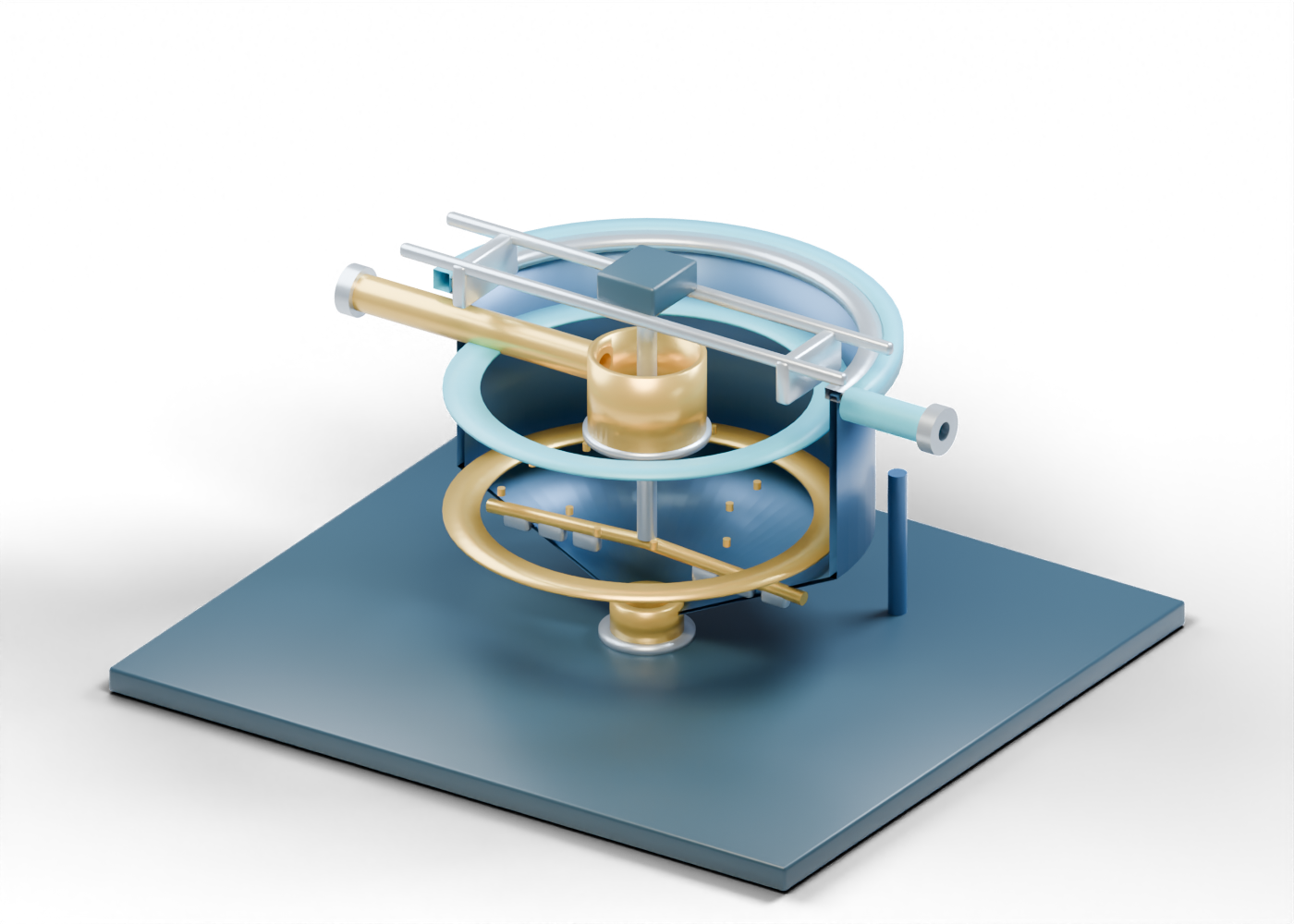
A Metso mineral-processing handbook names a feedwell, rake mechanism, overflow and underflow as conventional thickener roles. Our hollow suspended feed enters through a genuine opening in the central feedwell. The full circular tank wall is visible in the interactive model. Half section opens it to reveal the interior, and viewers can restore the complete wall. This generic scene establishes neither actual vessel dimensions nor distribution performance.
3. Read the upper water boundary
The overflow collection band has its own side bore and an open water outlet. In the AER-filed account, water released from settling can be reused in extraction. That statement is about the cited operation, not a quality test in our model. The blue fixed ring merely helps readers find the upper region. Water composition, actual turbidity, reuse suitability and any other destination require records beyond this illustration.
4. Find the lower material and static rake
A fixed rake arm and stationary solids marker show where mechanical and material roles can be discussed. They do not rotate, settle or predict rake torque. The gold lower-region ring sits above an invented open taper and a separate underflow neck. An underflow name does not tell us its solids concentration or final tailings-handling path.
| Illustrated role | Reader question | Separate evidence needed |
|---|---|---|
| Feed and feedwell | Where could slurry enter? | Feed source, rate and condition |
| Overflow band | Where could water leave? | Quality, amount and destination |
| Fixed rake | Where is a raking role? | Motion, torque and mechanical design |
| Lower ring and taper | Where is a denser region discussed? | Bed level and concentration |
| Underflow neck | Where does the lesson stop? | Pumping, blending and approved handling |
5. Challenge a performance claim
If a report states water recovery, outlet clarity or underflow solids, check its sampling point, method, period, feed conditions and uncertainty. A static cutaway cannot calculate any of those values. A vendor description establishes common equipment vocabulary, not an endorsement or a performance specification for the original AlbertaOil scene.
6. Continue through the independent lessons
Explore the 50-part thickener cutaway and select each boundary. Compare it with the separate flotation model to ask what happens after its remaining-slurry outlet. The models have invented, unmatched sizes and leave hydrocyclones, flocculant preparation, downstream blending and tailings disposition outside the scene.
For a cross-model view, use the six-stop AlbertaOil visual study to compare all five independent original equipment models, open exact parts, and keep whole-tailings classification distinct from the middlings-flotation question. The reading map is not a matched facility or operating route.