1. Start after primary separation
An AER-filed Horizon process plan describes one operator withdrawing middlings from a primary separation cell and processing them through secondary separation or flotation with added air. More froth can return toward primary separation, while remaining material moves to later handling. Those are process roles, not measurements or an equipment drawing for our generic illustration. The separate primary separation vessel lesson shows where its middlings boundary ends. These two original scenes are educational companions, not a matched facility.
2. Open the cell and find both inlets
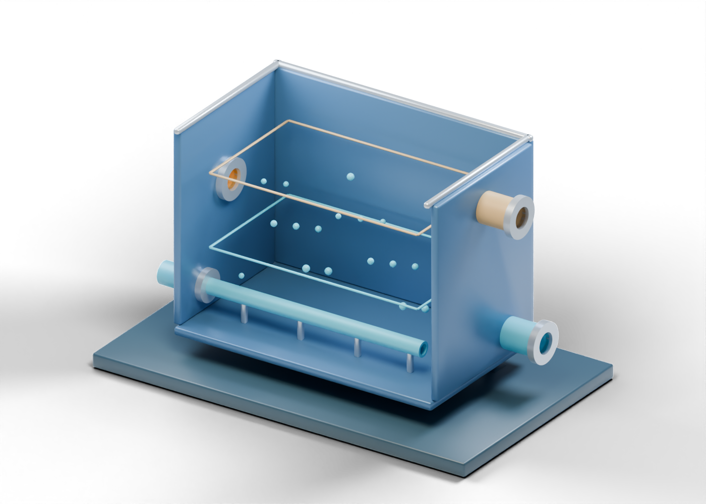
The 57-part interactive cell uses an invented rectangular form. Its complete feed-and-air wall contains two genuine side openings. The higher middlings feed and lower air addition are separate hollow boundaries. Real feed conditioning, line size, pumping, air pressure and reagent selection are outside the model.
3. Read the air and regions as static marks
The illustrative hollow air lance ends inside the cell. It is not a selected sparger. The fixed blue bubble is one of 18 stationary location cues. The gold froth-region edge and blue middlings edge are also fixed. None simulates mixing, attachment, rise speed, a measured interface or separation efficiency. The still image and initial interactive view hide the full front wall to make these teaching marks easier to see; the 3D file retains that wall and the viewer can restore it.
4. Keep the two exits distinct
The upper secondary-froth outlet and lower remaining-slurry outlet have independent wall bores and hollow ends. In the AER-filed operator account, additional froth has a return role and the remaining water, solids and bitumen move toward further treatment. Our model stops at its exits. It does not draw a return line, thickener, tailings pond or approved destination.
| Illustrated part | Useful question | What the image cannot establish |
|---|---|---|
| Middlings feed | Where does the lesson begin? | Actual feed rate or composition |
| Separate air inlet | Where could air be introduced? | Air supply or distribution design |
| Static bubble and region marks | Which roles are being discussed? | Motion, phase levels or recovery |
| Froth outlet | Which stream is separated conceptually? | Recovered bitumen quantity or quality |
| Remaining-slurry outlet | Where does this scene stop? | Final treatment or tailings approval |
5. Test any recovery claim against evidence
A recovery percentage needs a stated numerator and denominator, sampling points, test period and operating conditions. A coloured cutaway cannot supply those facts. The cited plan concerns one operator and should not be used to assign its performance, dimensions or cell configuration to this original model or another Alberta site.
6. Explore the connected lessons
Select the inlets, wall, air lance, fixed markers and outlets in the AlbertaOil 3D cell. Compare its incoming boundary with the primary vessel middlings outlet. Continue to the separate tailings-thickener guide to examine one later equipment role. The links join questions for readers; they do not establish compatible dimensions, a plant process flow diagram, operating instructions or an approved tailings route.
For a cross-model view, use the six-stop AlbertaOil visual study to compare all five independent original equipment models, open exact parts, and keep whole-tailings classification distinct from the middlings-flotation question. The reading map is not a matched facility or operating route.