1. Begin with mined oil sands, not a finished product
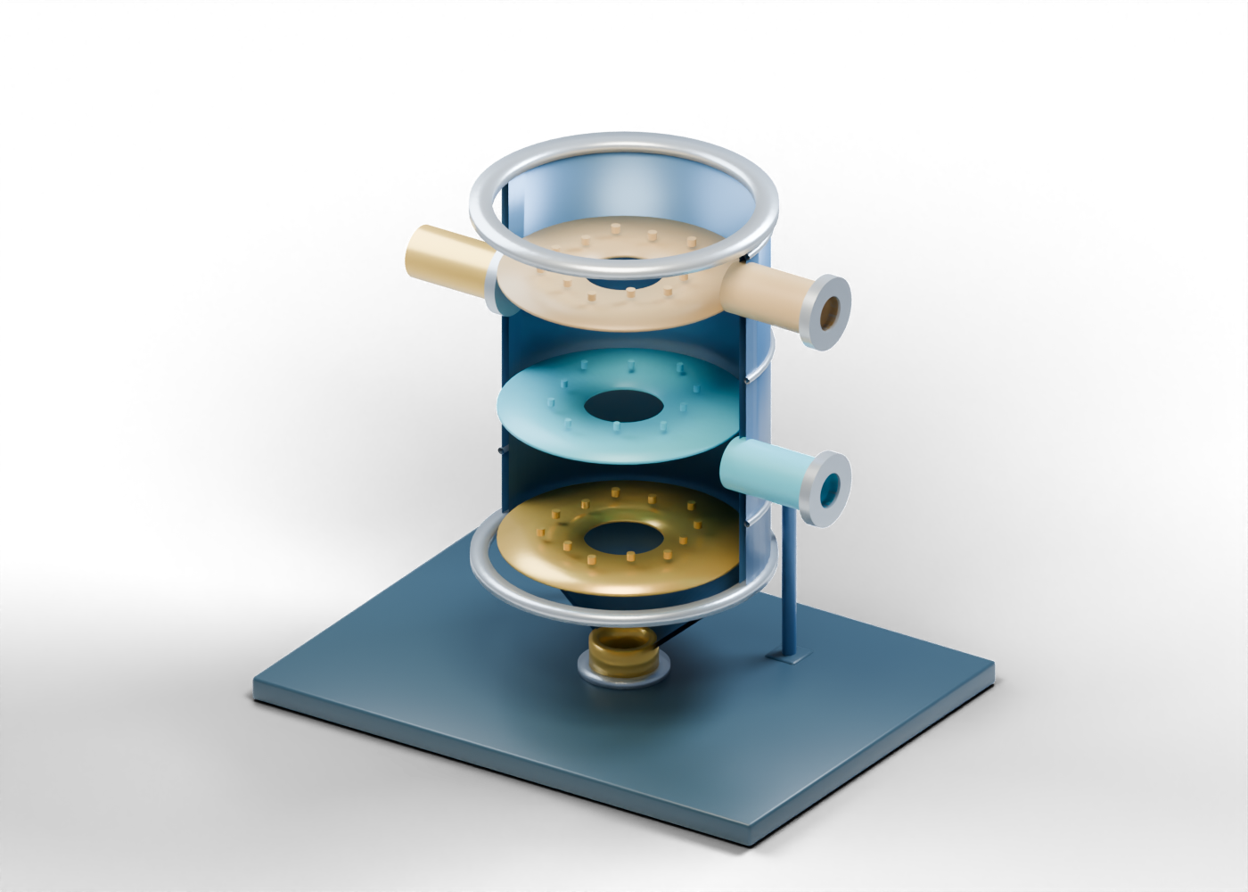
In mined-oil-sands extraction, a prepared slurry reaches an early separation stage. Alberta's oil-sands glossary describes a primary separation vessel as a large cylindrical tank, usually with a conical bottom, that produces bitumen-rich froth near the top. Our original interactive vessel illustrates that broad role. Its open slurry inlet is the start of this lesson, not a drawing of a mine's actual feed system.
2. Look through the complete shell
The bored barrel retains its entire inner and outer wall in the 3D model, with three separate side openings. The illustration removes the facing wall only in the still image so the distinct regions can be read. The shape and proportions are invented teaching geometry, not a vessel selected for a project.
3. Trace froth separately from middlings
An AER-filed Horizon process plan describes one operator's primary separation cell: upper bitumen froth moves to further froth treatment, while a middlings stream is withdrawn for secondary separation. In the model, the fixed froth region marker sits above the fixed middlings marker. These colours are reading cues, not measured layers or a simulation. The froth outlet and middlings outlet end at separate open boundaries; neither shows what happens inside the next treatment stage.
4. Follow the lower boundary
The same AER-filed plan distinguishes lower whole tailings from both upper froth and side-withdrawn middlings. Our complete conical wall narrows toward an open underflow collar. Fixed gold flecks suggest where a sand-rich region might be discussed. They are not particles in motion or a composition estimate. The model ends before actual classification, handling or any tailings destination.
| Visible element | Useful question | What the picture cannot prove |
|---|---|---|
| Slurry inlet | Where does the lesson begin? | Actual feed composition or rate |
| Upper froth outlet | Which stream needs further froth treatment? | Recovered bitumen quantity or purity |
| Side middlings outlet | Which stream could receive further separation? | Recovery from a secondary cell |
| Lower underflow | Where does the sand-rich stream leave? | Tailings treatment or disposal authorization |
5. Ask what a recovery claim is based on
If a project reports extraction performance, ask for the measured feed and output streams, sampling method, period, operating conditions and the definition of recovery used. The visible coloured bands cannot supply those values. Equipment dimensions, hydraulics, froth-treatment choices, tailings management and site approvals need project-specific records and qualified assessment.
6. Continue through the AlbertaOil lesson
Select the individual parts in the 61-piece 3D teaching vessel to compare its openings and the fixed region markers. Then use the separate SAGD steam-side guide to contrast mined-oil-sands extraction with an in-situ production route. These are different illustrations, not stages of one matched facility or an operating procedure.
For a cross-model view, use the six-stop AlbertaOil visual study to compare all five independent original equipment models, open exact parts, and keep whole-tailings classification distinct from the middlings-flotation question. The reading map is not a matched facility or operating route.