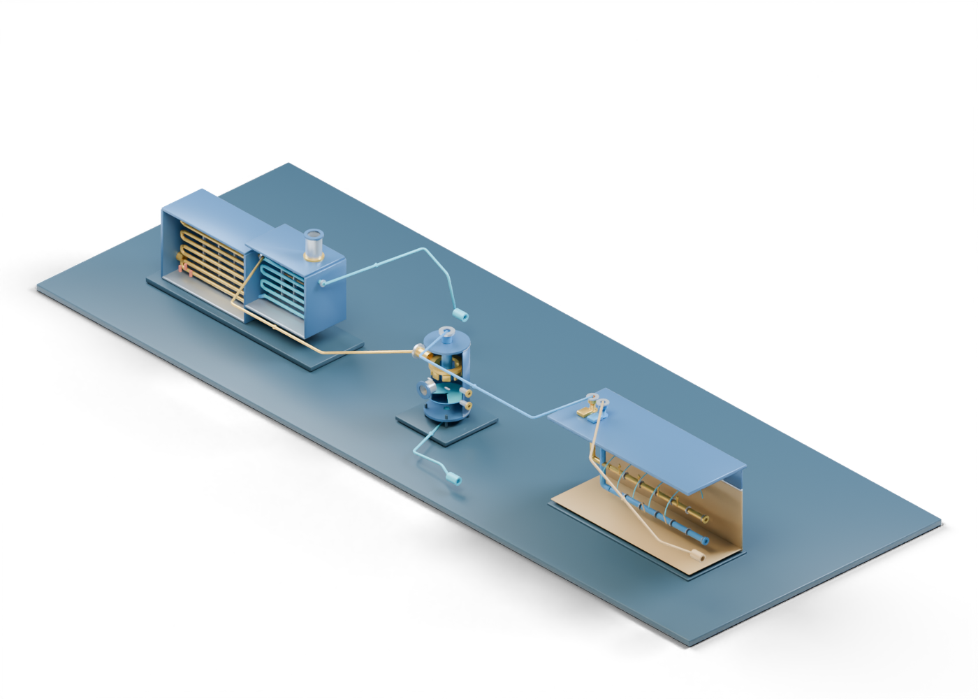
1. Read the process as separate jobs
Steam-assisted gravity drainage (SAGD) involves an upper injector and lower producer, as the Alberta Geological Survey explains. A public Alberta project description gives one example in which a once-through steam generator feeds a steam separator, with upper steam and lower liquid taking different destinations. Those are the broad roles in this original connected 3D scene. The illustrated positions and routes are not that project's layout.
Three independently detailed lessons remain available: the once-through steam generator, steam and liquid separator and injector–producer well pair. The combined scene helps readers move among their boundaries; it is not a matched set of equipment.
2. Start before the generator
The external feedwater boundary marks where a supply system would enter the picture. The blue feedwater relationship leads toward the separate generator's inlet. Neither route nor generator includes a treatment plant, source-water record or feed-pump duty.
Inside the generator, the convection tube run and radiant coil run are separately selectable. The sections explain a heating sequence. Tube colour is a reading aid, not a temperature or steam-quality measurement. The open wet-steam outlet is where this source model ends.
| Relationship in the 3D scene | What it helps locate | What it does not establish |
|---|---|---|
| Feedwater to generator | An external supply boundary | Water quality, treatment or pump capacity |
| Generator to separator | A possible wet-steam handoff | Steam condition, pressure or compatible pipe |
| Separator to injector | An upper steam-side destination | Injection-ready dryness or well control |
| Separator liquid to handling | A distinct lower destination | Blowdown rate, recycle or disposal |
| Producer to handling | A produced-fluid surface boundary | Production, separation or recovery result |
3. Keep the separator's two destinations distinct
Follow the gold generator-to-separator route to the vessel's open wet-steam inlet. Within the separator, an open annular guide marks an invented place to discuss internal guiding. Its geometry is not a specified separator design or removal result.
The upper steam-side route leaves from the vessel's upper steam outlet. The lower liquid route starts at a different opening and ends at a separate handling boundary. The blue liquid marker inside the vessel is a static illustration, not a measured level.
4. Follow injection and production separately
The upper relationship reaches the injector boundary. The AGS explanation describes steam entering the upper horizontal well and heated bitumen and condensed water moving toward the lower producer. Our well-pair steam-chamber outline is a visual teaching mark, not a predicted chamber.
The producer well path returns to a separate surface end. Follow the brown produced-fluid relationship to its external handling endpoint. No surface separation equipment is attached in this scene.
5. Notice the missing water loop
The Alberta Energy Regulator's in-situ water-use overview explains why water treatment, produced water and reuse matter in real operations. This illustration ends at both liquid-handling boundaries. It does not close the path from produced fluids back to generator feedwater. A diagram that simply draws a loop would not prove recovery, treatment quality or permission to dispose of any water.
Project headlines about steam-to-oil ratio, water recycling, injection pressure or emissions need dated, site-specific records and clear definitions. The colours, pipe-like lines and arrows here convey relationships, not those results.
6. Inspect the whole scene, then go deeper
Open the connected SAGD process scene and use its five stream controls to compare the paths. Focus the feedwater entry, generator heating section, wet-steam transfer, separator vessel, upper steam route, liquid boundary, injector and producer exit. Each standalone model has more detailed part studies. They remain separate schematic lessons with open ends, not an engineered or operating Alberta plant.