1. Start with abrasive whole tailings
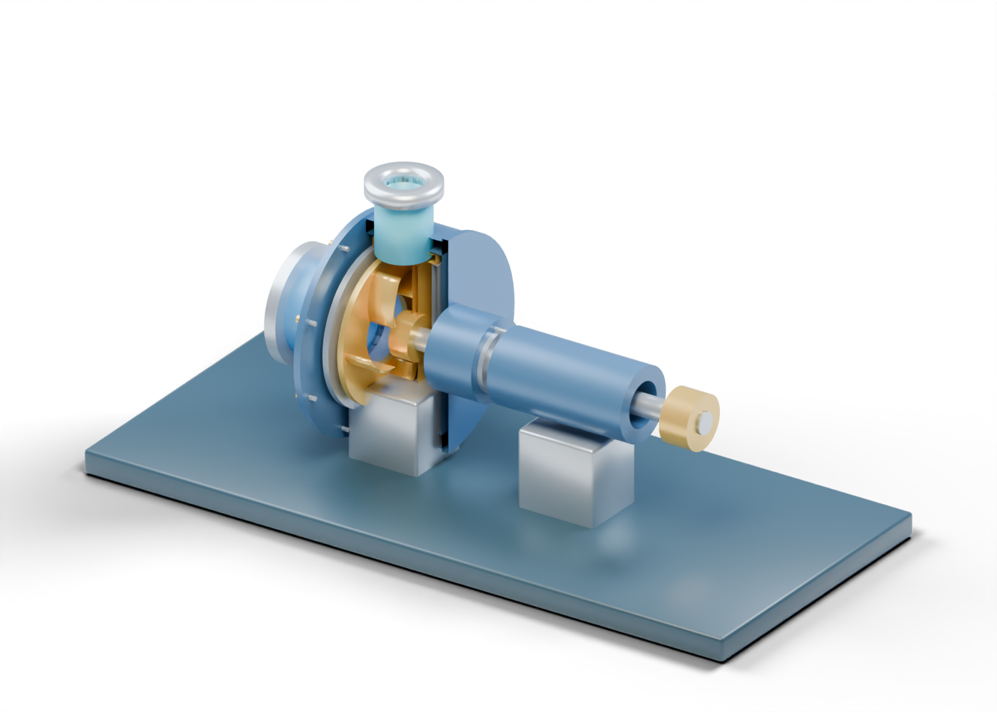
An AER-filed Horizon measurement plan describes one operator pumping primary-separation whole tailings toward classification cyclones. It does not name this illustrated pump as installed equipment. The separate primary-vessel underflow marks an upstream teaching boundary; the 74-part interactive pump begins at its own open axial suction neck. There is no joined pipe between the scenes.
2. Find the wear-facing wet end
KSB's centrifugal-pump lexicon describes abrasive-slurry service and replaceable wear-facing components. In this original concept, an open throat-bush sits near the impeller eye, separate from the front side liner and rear liner. The complete outer casing encloses those parts and has a real upper discharge opening. The individual rings identify roles; their shapes do not specify a material, running clearance or replacement interval.
3. Look between two impeller shrouds
A general Metso slurry-pump handbook distinguishes impeller, throat-bush and shaft-seal components. The model's open front shroud admits the conceptual feed, and five separate curved vanes sit between it and the back shroud. Select one vane to see the distinction. Neither the vane count nor curvature is a selected product or evidence for a pump curve, pressure or efficiency.
4. Follow discharge and the separate shaft-side parts
The hollow upper outlet crosses the actual outer-casing bore and ends before any pipeline. Behind the wet end, the shaft sleeve occupies a different role from a packing location. The bearing housing has independent race and rolling-element cues. These are component-reading aids, not proof of seal-water needs, leakage, lubrication, bearing loads or a safe operating arrangement.
| Visible element | Useful question | What the picture cannot prove |
|---|---|---|
| Suction and throat-bush | Where does material enter the wet end? | Feed rate, solids content or clearance |
| Side liners | Which surfaces may be wear-facing? | Material or wear life |
| Vanes and shrouds | Which pieces form illustrated passages? | Pump curve or efficiency |
| Upper discharge | Where does the model end? | Pipeline pressure or destination |
| Sleeve and packing | Where is a shaft-seal region? | Leakage or seal-water design |
5. Separate this model from a service decision
Real slurry-pump selection needs site-specific fluid and solids data, duty point, materials, clearances, sealing method, driver, guarding and maintenance assessment. Neither the picture nor a generic source can establish those for an Alberta facility. The four small coloured marks are stationary reading cues, not particles, trajectories or a measured size distribution. Compare the independent general centrifugal-pump model for the broad pumping principle; it is not a compatible alternative specified by this guide.
6. Continue to classification, without assuming a plant layout
The AER-filed Horizon account then discusses hydrocyclone classification. Explore the independent whole-tailings classification model and OilNews classification guide to compare a pump's transfer role with separate coarse underflow and fines-rich overflow roles. These links form a learning path, not one operator's equipment list, process flow diagram or operating instruction.
For a cross-model view, use the six-stop AlbertaOil visual study to compare all five independent original equipment models, open exact parts, and keep whole-tailings classification distinct from the middlings-flotation question. The reading map is not a matched facility or operating route.