1. Follow glycol beyond the contactor
The glycol contactor removes water from a natural-gas stream by bringing the gas into contact with circulating glycol. The glycol that leaves carrying more water is called rich glycol. To use it again, a wider dehydration system reconcentrates it; the still and reboiler illustrate part of that regeneration role. The historical U.S. EPA/GRI glycol-dehydrator study diagrams the general absorber/regenerator relationship. SLB's glycol dehydration overview likewise describes rich glycol returning for reconcentration, water leaving and lean glycol returning toward gas contact. Neither source validates our geometry or identifies a particular Alberta plant.
The optional flash-tank guide covers a separate rich-glycol role that may appear between absorption and regeneration. A flash tank is not represented inside this still/reboiler model, and the three independently authored 3D assets are not a matched unit.
2. Read the original cutaway
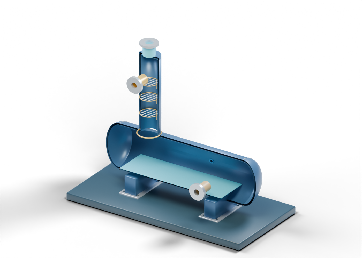
Our 48-part original 3D assembly puts a vertical still-region shell over a horizontal reboiler-region kettle. An actual geometric opening joins the two hollow shells. A separate side neck names the rich-glycol feed; a top neck names the water-vapor overhead; a lower side neck names the lean-glycol outlet. They remain open boundaries rather than connected, rated piping. Three grids inside the still have individually selectable crossbars. They are visible location markers, not selected trays, packing or tested contacting surfaces.
The thin blue plane in the kettle marks a conceptual liquid region. Three small gold members below it identify a heat-transfer region for discussion. No burner, firetube, heating utility or duty is modeled. The render cannot show a temperature profile, vapor rate, solvent concentration, water-removal efficiency or gas dewpoint. The still hides one facing enclosure half for visibility; the interactive model retains the full shells.
3. Keep each process boundary separate
| Visible region | What the teaching model shows | What a real installation needs as evidence |
|---|---|---|
| Rich-glycol feed | A drilled side opening and hollow neck | Feed composition, rate, pretreatment and actual line arrangement |
| Open still grids | Three separate, inspectable location markers | Selected internals, hydraulics and stripping result |
| Kettle and blue plane | A hollow enclosure and static liquid marker | Heat source, duty, inventory, temperature and level control |
| Water-vapor overhead | A bored top plate and open neck | Actual vapor composition, condenser or vent route and emission controls |
| Lean-glycol outlet | A separate lower side opening | Measured glycol quality, cooling, pumping and return connection |
An additional open neck labels an illustrative instrument boundary. It does not supply a sensor, control logic, relief device or protection system. Eight bores in the saddle feet mark locations, not foundation or structural proof. The model does not specify materials, pressure ratings or any operating or maintenance procedure.
4. Ask what a project claim proves
If a project story says a dehydration unit improves gas quality, first identify the named facility and equipment status. A procurement image is not a commissioned unit. A design target is not a measured outlet. Ask which dated feed and gas-outlet analyses substantiate the drying claim, which records describe glycol circulation and regeneration, and what the actual overhead stream does after leaving the equipment. Environmental claims require site-specific controls, measurements and permits. The U.S. historical study provides process context only; it does not establish current Alberta requirements or a recovery figure for this invented arrangement.
5. Inspect the named parts in 3D
Open the still and reboiler and use its guided studies. Focus the rich-glycol feed, middle still grid, overhead boundary, kettle wall and lean outlet.
Compare the contactor guide and optional flash-tank guide to separate absorption, flashing and regeneration.