1. Place the optional vessel in the loop
A glycol contactor and a glycol regenerator do different jobs. The contactor transfers water from wet gas into circulating glycol; regeneration removes water from the rich glycol so it can return. A flash tank may sit in the rich-glycol loop between them, giving lighter hydrocarbons a separate gas-side exit before regeneration. The U.S. EPA/GRI's historical study shows the flash tank as optional in its block flow diagram and describes that placement in section 3.1. The study is process context, not evidence for a particular Alberta installation or this invented vessel geometry. U.S. EPA/GRI: glycol dehydrators, Figure 3-1 and section 3.1.
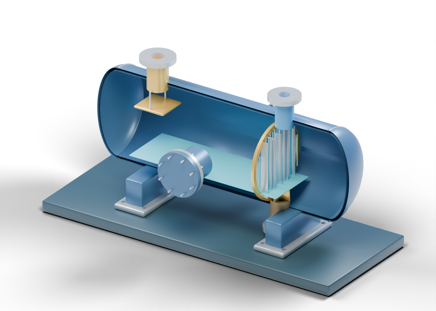
Our original 3D cutaway has 73 named selectable mesh parts. It offers separate rich-glycol inlet, upper flash-gas outlet and lower rich-glycol outlet boundaries. The Alberta-blue shell, prairie-gold inlet diverter and open lattice are teaching shapes created for this site. No EPA illustration, plant survey, product CAD or dimension was imported.
2. Follow three boundaries before reading internals
The upper inlet neck aligns with an actual opening through the vessel wall. The flash-gas neck is a second upper opening, away from the inlet. A lower outlet marks rich glycol leaving toward equipment that is not modeled here. These are independent, open geometric boundaries. They do not establish a piping route, fuel-gas destination, pressure-control valve or actual flow.
The glycol contactor guide examines the separate absorber-side role. Its original model and this tank have independently invented dimensions and are not a matched installation. The regenerator, pumps, vent controls and downstream treatment still need their own models and evidence.
3. Inspect visible markers without inferring separation
A flat gold diverter sits below the inlet as a place to discuss distribution. Twenty-seven individually selectable straight members form an open lattice near the gas-side outlet. The thin blue plane is a static liquid-interface marker. These details improve the explanation, but none is a selected demister, measured liquid level, residence-time calculation, hydrocarbon analysis or proof of gas capture.
The interactive model retains the shell and closed access cover. The poster removes one facing enclosure half only for visibility. Eight smooth stud markers and corresponding cover bores are geometric locations, not a pressure-vessel closure design or instructions for opening a vessel.
4. Separate claims from required evidence
| Original scene region | What can be inspected | What still needs independent evidence |
|---|---|---|
| Rich-glycol inlet and diverter | Actual inlet opening and separate flat marker | Feed composition, pressure letdown, distribution and erosion |
| Flash-gas outlet | Separate upper neck and bored flange | Gas rate/composition, recovery destination and emissions compliance |
| Lower glycol outlet | Separate liquid-side opening | Liquid quality, control, downstream connection and regeneration |
| Lattice and liquid marker | Open members and a static interface position | Mist removal, level, hydraulics and separation performance |
| Closed access and saddles | Solid cover, stud locations and bored feet | Pressure rating, safe access, support loads and foundation |
EPA discusses flash tanks in the context of emissions, but a photograph or our render cannot establish a methane-recovery percentage. Compare a project claim against the named facility, its installed equipment, dated measurements, operating conditions, actual gas handling and permit record. No numerical EPA estimate is applied to this drawing.
5. Read the equipment in an environmental context
The historic EPA study says a flash tank is not universal in glycol dehydration. Whether one is fitted, and how flash gas is handled, depends on the actual installation and its controls. A tank icon by itself cannot show whether gas goes to fuel use, recovery, a control device or another destination. The gas boundary in our model deliberately ends at an open flange.
This article is a source-linked reading aid, not current regulatory advice, an operating sequence, equipment selection or an engineering assessment. For any real facility, use current site-specific records and applicable requirements rather than this generic historic process study.
6. Inspect the original 3D parts
Open the complete flash-tank concept for the intact vessel, ten guided stops and a reveal-internals view. Inspect the rich-glycol inlet, inlet diverter, mist-region member and closed access cover as exact named parts.
Compare the contactor guide to keep absorption, optional flashing and regeneration distinct. The two original 3D vessels are independent concepts, not a complete glycol plant.