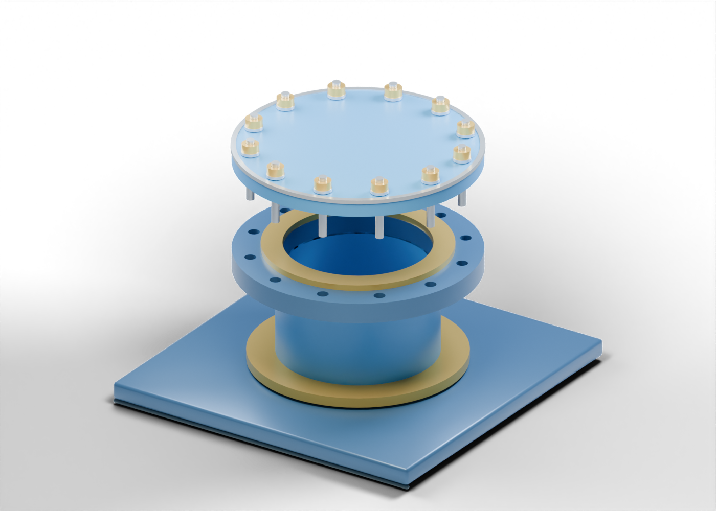
1. Recognize the access boundary
A manway is a closure at an access opening on pressure equipment. It is one part of a much larger pressure boundary and requires equipment-specific engineering and controls. The ASME BPVC overview describes broad pressure-vessel construction and inspection subjects. Our original 46-part manway model is a generic teaching assembly, not a chosen design, a real Alberta vessel or an instruction to enter or open equipment.
2. Follow the opening into the neck
The flat wall-region coupon has a genuine central hole. It is deliberately flat so the passage is easy to inspect; a real cylindrical vessel shell is a separate design question. The complete hollow manway neck sits over that opening, while the inner bore edge is independently selectable. These visible openings establish location, not wall thickness, access size, joint strength or pressure capacity.
3. Keep reinforcement separate from appearance
The gold reinforcement-location ring tells a reader where to ask about a shell opening and surrounding material. A visible ring cannot prove that a nozzle is reinforced adequately, welded correctly or suited to a particular fluid, pressure or temperature. Real evidence comes from the vessel's applicable design and inspection records, not the colour or proportions of this illustration.
4. Compare flange, gasket and blind cover
The closure flange has twelve real geometric fastener holes around an open centre. A separate ring gasket envelope lies inside that invented bolt circle, and the blind cover has matching holes but a solid centre. ASME's PCC-1 overview discusses pressure-boundary bolted joints with ring-type gaskets as a specialized assembly subject. This model does not reproduce a standard detail or establish gasket material, facing, compression or leak-tightness.
5. Read one fastener set without inferring a method
One smooth stud marker, its separate bored washer and open nut marker can be selected individually. The twelve positions are invented. The model gives no thread form, bolt grade, preload, torque, tightening pattern or removal sequence. The still image lifts the closure set to reveal parts; the interactive model begins with the cover in a closed static position. Neither image depicts a safe way to open a vessel.
| Visible piece | Reading question | Not established |
|---|---|---|
| Wall coupon and neck | Where is the access passage? | Qualified vessel shell or weld |
| Reinforcement ring | Where would reinforcement be assessed? | Adequate reinforcement area |
| Closure flange | Which holes surround the opening? | Pressure class or facing |
| Ring gasket and cover | Which part closes the central passage? | Seal selection or leak test |
| Stud, washer and nut | Which pieces share a fastener position? | Grade, preload or opening method |
6. Check a real vessel claim against its records
When a report discusses vessel inspection, access or replacement, identify the actual equipment and the document supporting the claim. A manufacturer's chosen closure, a recorded inspection finding and a completed repair are different kinds of evidence. Use the interactive manway lesson to learn part names, then compare the separate vertical two-phase separator and gas-liquid coalescer to see manway locations in larger teaching assemblies. None of the three illustrates a shared plant, qualified pressure boundary, confined-space assessment or safe entry procedure.