1. Put the packer in the completion
A production packer sits downhole where the tubing runs within casing. The tubing offers a production conduit; the space between tubing and casing is the annulus. SLB's packer glossary describes a typical assembly with an anchoring arrangement such as slips and an expandable elastomeric element to isolate that annulus. SLB's introduction to well completions places the packer in a wider tubing and casing system. These references support general roles, not our illustrated dimensions or an installed well.
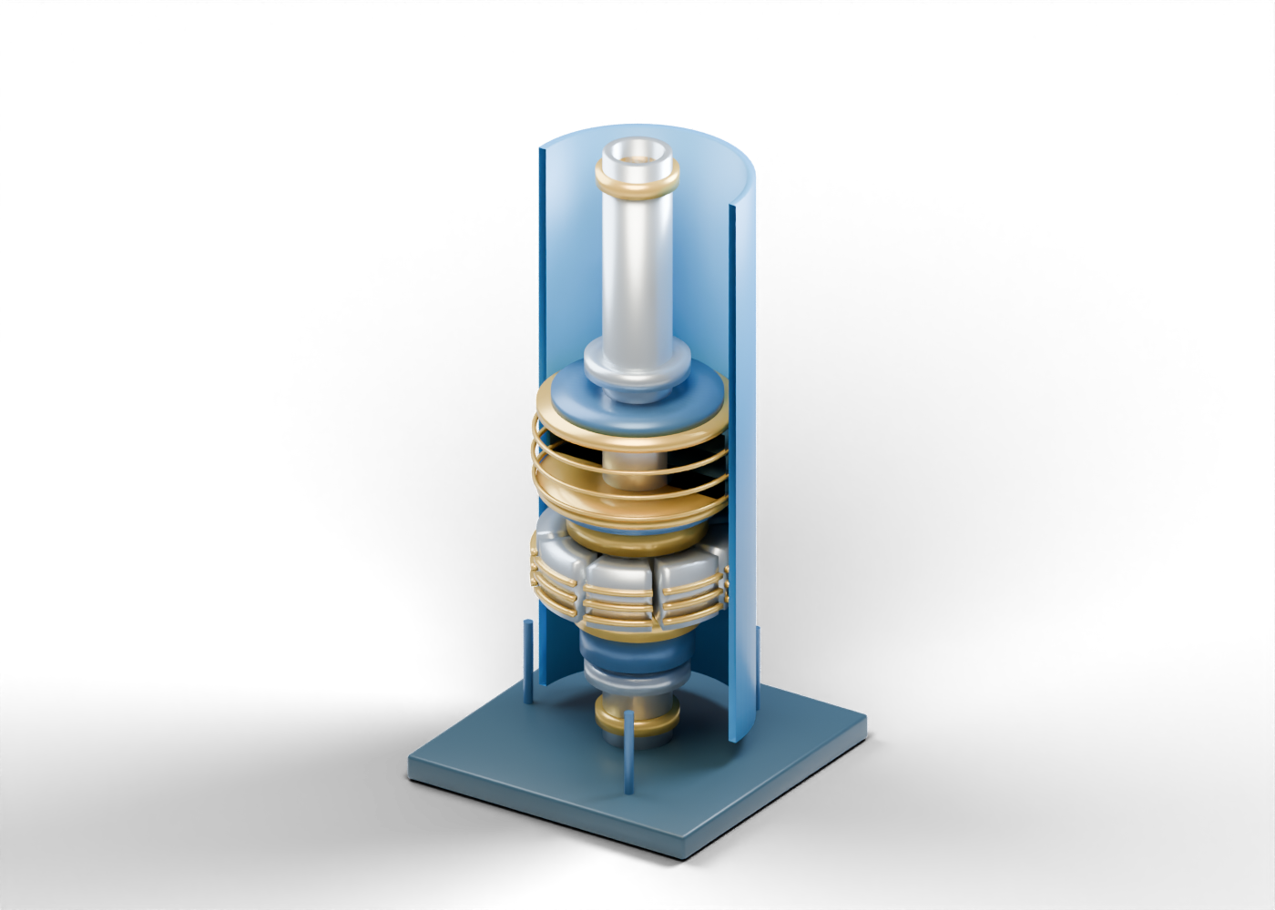
The original AlbertaOil packer lesson shows 55 selectable parts in a static tubing-casing section. The blue casing, steel tubing, dark element bands and gold markers are independent teaching geometry.
2. Follow the bore, then the annulus
Start at the open production tubing mandrel. Its hollow centre helps locate a possible production path through the illustrated assembly. The surrounding complete casing wall is a separate open-ended enclosure. The annular space lies between them. Neither opening establishes a flow rate, connection specification or pressure integrity.
Only the poster removes the facing portion of the casing and element surfaces to reveal the interior. The interactive model retains the complete parts; use Reveal internals to inspect them. This is a viewing control, not a setting or service step.
3. Identify the sealing-element role
Three distinct elastomer element bands stand near the casing wall. The upper retainer and lower backup marker make their region readable. SLB describes expandable elastomeric elements as a common means of creating a packer seal. Our shapes deliberately retain a small radial gap and have no selected compound, compression, contact or tested differential pressure.
| Original element | What it locates | What it cannot establish |
|---|---|---|
| Hollow tubing mandrel | A central production-path concept | Flow rate or pressure integrity |
| Separate casing wall | The outside boundary of an annular region | Casing grade, size or suitability |
| Three dark element bands | An expandable-seal role | Actual casing contact or hydraulic isolation |
| Eight slip sectors and ridges | An anchoring role | Casing bite or axial-load capacity |
| Retainers, cone and sleeve markers | Places to discuss a setting concept | A working setting or release mechanism |
4. Keep gripping separate from sealing
The first grip slip sector is one of eight separate static sectors. Its second ridge is one of 24 individually selectable markers. Slips introduce an anchoring role; the elastomer bands introduce a sealing role. Seeing both shapes does not show that either has engaged casing.
A lower cone marker and setting-sleeve envelope are location cues only. The assembly does not move, set, release or transmit a calculated force. It is not a retrievable, permanent, hydraulic-set or other selected packer design.
5. Ask for the evidence behind a barrier claim
A statement that a well's annulus is isolated needs evidence tied to its selected equipment and actual well. Ask which packer and completion were installed, what pressure and temperature conditions apply, which materials contact the produced fluids, and what testing or monitoring supports the reported barrier status. A cutaway, a catalogue image or this model alone cannot answer those questions.
Likewise, a news item about a production change should distinguish measured well performance from equipment purpose. This guide reports no well test, incident, installation, capacity, fluid route or safe operating procedure. It does not authorize intervention or establish regulatory compliance.
6. Compare independent completion roles
Explore the full 3D packer and its separate casing, bore, element and slip parts. Then compare the electric submersible pump guide and progressing cavity pump guide to separate annular isolation from artificial lift. The wellhead tree model illustrates a surface role. These are independent teaching scenes, not a matched completion, verified pressure system or recommended equipment combination.