1. Where an ESP fits
An electric submersible pump (ESP) is an artificial-lift arrangement that uses a downhole electric motor to drive a multistage centrifugal pump. SLB's ESP overview identifies the motor, protector, intake, pump and power-cable roles. The Baker Hughes Submersible Pump Handbook provides broader assembly context. These sources establish the general vocabulary; no vendor artwork, CAD, dimensions or performance data were copied.
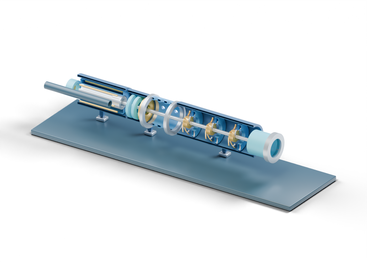
The original AlbertaOil 3D ESP lesson is a static, horizontal display with 79 selectable parts. Its Alberta-blue, prairie-gold and steel poster sections the facing enclosures for reading. The interactive browser model retains complete housings. It is an educational component map, not a depiction of a selected well or product.
2. Start with the motor and protector
The complete motor housing contains a separate stator envelope around a rotor envelope. Six small rods, including winding-location cue 1, identify a region to discuss electrical windings. They are not conductors sized or insulated for service. The open lower sensor-location sleeve and static core are only an uninstrumented position marker.
The complete protector housing sits between the motor and intake. Two barrier-location rings and a thrust-bearing location distinguish broad roles without modeling a working seal, bearing load, lubricant system or motor protection. The illustration has no voltage, current, temperature, pressure or service-life basis.
3. Look through the intake
The complete bored intake wall contains twelve real side openings. Their invented count and pattern make an intake region visible; they are not a selected screen or gas-handling device. The lower and upper collars remain open in the interactive geometry. No fluid enters this static scene, and the poster cannot establish an inflow rate, gas fraction or solids response.
| Visible part | Helps locate | Does not establish |
|---|---|---|
| Motor rotor and stator | Electrical drive roles | Motor rating, cooling or insulation |
| Protector rings and bearing marker | A section between motor and intake | Seal integrity or thrust capacity |
| Twelve intake openings | Possible fluid-entry region | Screen or gas-separation performance |
| Three impeller and diffuser pairs | Repeated centrifugal-stage roles | Head, flow, efficiency or selected stage count |
| Open discharge and cable route | Two different external boundaries | Tubing connection or electrical termination |
4. Compare impellers and diffusers
The model uses three separate teaching stages. In the first, select an impeller vane and the diffuser carrier; then inspect a diffuser vane in stage two and the third-stage impeller hub. Eighteen gold impeller vanes and fifteen distinct diffuser vanes make the repeated roles individually inspectable. Their curves, count and spacing are invented. Nothing turns or moves fluid, and no pump curve or pressure rise was calculated.
The static shaft-axis cue helps follow alignment through the display. It does not certify shaft design, torque transfer, bearings or fit. A real ESP selection needs well and fluid data plus qualified engineering and manufacturer specifications.
5. Follow two separate external paths
The open produced-fluid discharge sleeve marks an outlet beyond the stage section; production tubing and a rated connection are outside the scene. The external cable jacket cue runs alongside the assembly, with three conductor-location rods and a lead-entry marker. These are visual route cues, not an energized cable, termination, safety instruction or electrical design.
The progressing-cavity-pump lesson shows a rotor-within-stator pumping principle, while the rod-pump lesson shows a reciprocating one. A surface centrifugal-pump lesson helps compare impeller vocabulary. These independent models do not rank lift methods for a particular well.
6. Inspect the complete model
Open AlbertaOil's interactive ESP atlas page and select the motor housing, protector, intake, first impeller vane, second-stage diffuser vane, discharge and cable jacket. The poster removes facing halves for visibility; the delivered 3D model retains them. Neither version is an installation drawing, operating procedure or service qualification.