1. Start with a field-production example
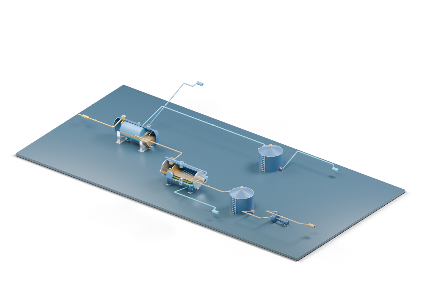
An oil battery can bring separation, treatment and storage roles together before fluids move to later destinations. The U.S. EPA's 2019 production overview, Section 3.1.2 and Figure 3-2, describes one example that includes a separator, heater treater and storage. It also makes clear that actual battery arrangements vary. The AlbertaOil connected 3D lesson is our own teaching layout, not a depiction of that EPA figure or an Alberta installation. Its equipment positions, connections, colours and dimensions are invented.
2. Separate the incoming stream
At the incoming production boundary, the illustrated stream reaches the three-phase separator vessel. The separator's independent gas outlet flange, oil outlet flange, and water outlet flange make three onward roles visible. They do not prove a separation efficiency or product quality. Follow the oil relationship into the treatment role; the gas and water take different paths.
3. See where further oil treatment can fit
The separated oil or emulsion reaches the heater-treater vessel wall through its emulsion feed neck. Inside the separate model, a static region locates a possible heating role. The higher oil exit continues toward oil storage. The lower water draw and upper gas boundary end at their own open further-handling boundaries. No fuel system, heat duty, emulsion chemistry, level control or achieved separation is calculated.
4. Distinguish storage from treatment
The oil storage tank and produced-water storage tank are two instances of the same original tank model. Their separate labels explain the teaching roles; neither tank illustrates a selected material, containment system, vapour system, measurement or permitted handling destination. The separator-water path reaches the water tank, while the treater-water branch remains separate and open. The illustration does not silently merge those branches into a designed manifold.
| Visible path | What the scene shows | What remains unverified |
|---|---|---|
| Incoming to separator | A declared arrival relationship | Well composition, protection and flow |
| Separator oil to treater | An example treatment role | Chemistry, heat duty and oil quality |
| Treated oil to tank and pump | Storage and transfer roles | Tank design, pump selection and export specification |
| Separator water to water tank | A separate storage branch | Treatment and approved destination |
| Gas and treater water exits | Open further-handling boundaries | Compression, vapour control, disposal and emissions |
5. Trace transfer without implying an export system
Oil leaves the tank's withdrawal connection toward the centrifugal pump volute. The pump's discharge outlet reaches an open oil-handling boundary. A real transfer system needs selected equipment, piping, controls, containment, measurement and quality evidence. This static arrangement provides none of those results. The coloured route tubes and arrows are teaching annotations, not fabricated pipe or a computed flow field.
6. Open the detailed lessons
Use the connected AlbertaOil scene to select exact parts, hide one stream at a time and trace ten declared relationships. Then inspect the independently authored three-phase separator, horizontal heater treater, storage tank and centrifugal pump. The scene is a starting point for understanding terms in industry news. It is not a P&ID, equipment selection, safe operating procedure or technical approval.