1. Read a circulation system as several roles
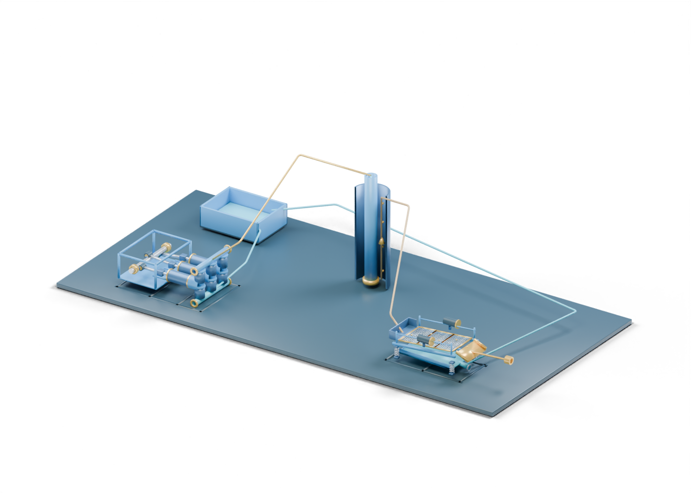
The SLB Energy Glossary describes a broader drilling-fluid path involving main rig pumps, surface lines, drillstring, bit, annular return, mud-cleaning equipment and tanks. The Alberta Energy Regulator's drilling overview explains why fluid is pumped through a well: pressure control and removal of rock fragments. Our original 212-part 3D relationship map brings a three-bank mud-pump model and open-screen shale shaker into one invented scene. It shows useful spatial questions, not a particular rig, a working hydraulic circuit or an operating procedure.
2. Begin with the surface tank and pump question
At the left, the open tank floor and static colored fluid surface identify an inventory role. The tank-to-pump route ends at a reused hollow suction manifold. The separate crankshaft lets you inspect the drive region in the same scene, or open the standalone pump cutaway for all three banks. A real system may need precharge, conditioning, valves and instrumentation that are absent here. The picture supplies no fluid properties, tank capacity, suction conditions or pump duty.
3. Compare the down-string and annular spaces
Follow the gold discharge relationship toward the complete hollow drillstring. A separate down-string cue occupies its open centre. Near the bottom, the bit-location collar marks where our simple section stops; it is not a selected bit or nozzle. The complete outer well wall surrounds an open annular region, and return cue is separate from the inner path. The still image sections the facing wall for reading; the interactive wall remains whole and can be revealed or sliced. No casing, formation, well-control equipment, measured fluid rate or pressure calculation is supplied.
4. Follow returns to the first visible screen
Four frozen gold fragment markers suggest what a reader should look for in a returning stream; they are not particle trajectories. The surface-return relationship meets the shaker feed box. The shaker's first open teaching lattice has real enlarged gaps in the exported model. The standalone shaker explorer shows the other screens and drive markers in detail. Real screen grade, fluid loading, separation result and the rest of a mud-cleaning train require actual equipment evidence. NOV's drilling-fluid processing overview describes additional processing and control roles without defining this invented layout.
5. Keep the two surface exits distinct
The recovered-fluid route points back toward a tank role, while the cuttings route reaches a separate open waste boundary. These are conceptual exits. The AER's Directive 050 page covers drilling-waste management; a visible chute or arrow does not classify waste or approve disposal.
| Visible cue | Useful question | Missing evidence |
|---|---|---|
| Tank and pump | What fluid and suction equipment feed the actual pump? | Inventory, conditioning, precharge and pump records |
| Inner pipe and annulus | What actual well geometry and pressure conditions apply? | Well program, measurements and well-control evidence |
| Open shaker lattices | Which screens and downstream cleaning steps are installed? | Equipment selection and field separation results |
| Separate cuttings boundary | What handling route is approved? | Waste sampling, classification and disposition records |
6. Use the map beside an Alberta drilling report
Open the interactive relationship scene, select one route at a time and return to the source report with a named well, rig or operator, date and measured claim. The path controls help distinguish component roles and unresolved boundaries. They cannot verify circulation efficiency, well safety, waste approval, or the performance of the equipment shown.