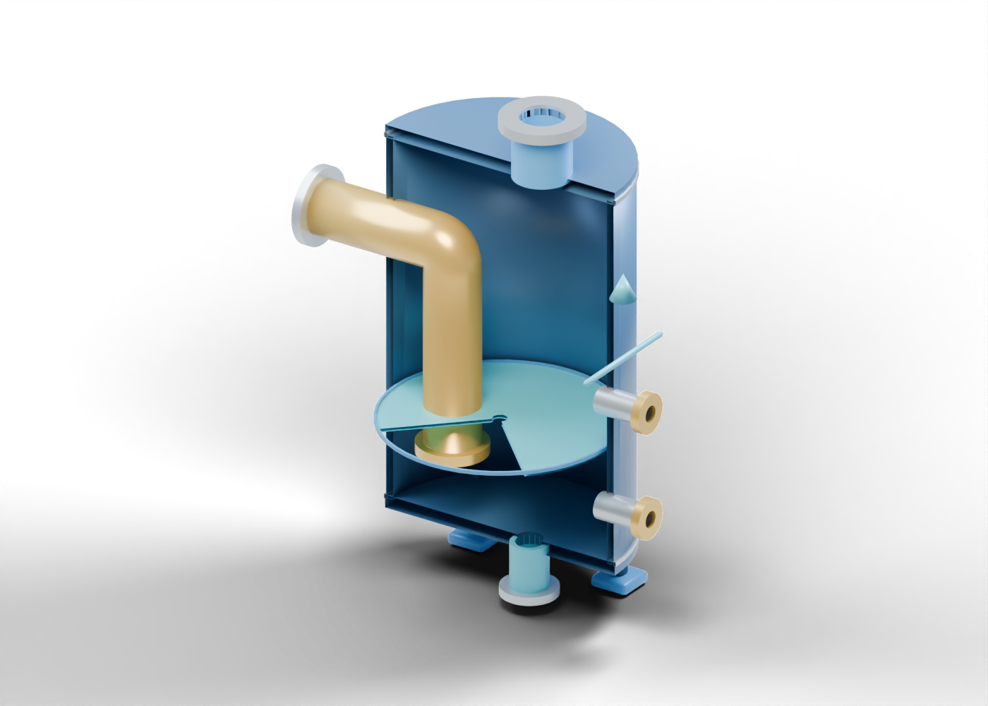
1. Place the vessel in the flare train
A flare system can include several pieces with different jobs. The U.S. EPA flare chapter describes a knock-out drum for removing entrained liquid and a possible downstream liquid seal before the stack. Some arrangements combine roles; this guide isolates the seal vessel so the boundaries are easier to compare. Alberta's Directive 060 is the regulatory starting point for upstream flaring, incinerating and venting. Neither reference approves the illustrated vessel for an Alberta installation.
The knock-out drum guide explains the earlier liquid-removal role. Its vessel and this one are separate illustrations, not a connected plant.
2. Follow the inlet below the liquid surface
Open the bent inlet and submerged leg in the 3D view. It enters through the upper side of the vertical shell, bends inward and ends below a pale blue surface. The header-side opening and the submerged end are both open geometry. The blue plane is a static level marker, so its position helps explain the concept without showing actual liquid inventory, hydrostatic head, gas bubbling or a maintained seal.
The hollow vessel wall surrounds the marker. The upper and lower closures retain distinct bored openings. These details let you follow the drawn route without treating the model as a hydraulic simulation.
3. Keep every exit distinct
| Boundary | What the illustration identifies | Evidence a real installation would need |
|---|---|---|
| Header-side inlet | Open bent leg ending below the blue marker | Header arrangement, fluid conditions and design basis |
| Upper gas outlet | Separate open neck above the illustrated surface | Actual downstream piping, stack and operating conditions |
| Lower liquid drain | Independent lower passage | Liquid handling and approved destination |
| Two level connections | Separate upper and lower side openings | Selected instruments, controls and operating records |
Select the upper gas outlet, lower drain, lower level boundary and upper level boundary to see where the illustration stops. None is connected to a real pipe, instrument, pump or control system.
4. Understand what the image cannot prove
A liquid seal is discussed in flare-system design because of its potential protective role. This drawing cannot establish protection. It has no pressure, flow, purge, gas-composition, liquid-head or transient calculation; no tested flame barrier; and no selected materials or control settings. Its arrow is a reading aid, not measured gas movement. A plausible visual path is not evidence that a flare can be operated safely or that a project meets Directive 060.
The four support feet have visible opening locations, but they do not demonstrate structural capacity or foundation design. Nothing here is an equipment selection, operating sequence or emergency procedure.
5. Read project claims carefully
If a project announcement says a flare upgrade cuts emissions or improves safety, ask which site and equipment it concerns, whether the work was proposed, built or commissioned, and which dated records support the claim. Separate a design target from measured operation. Look for the full system boundary: collection header, liquid removal, any seal, stack, combustion equipment, controls and liquid handling. This single vessel cannot stand in for that evidence.
6. Explore the separate components
Start with the complete liquid-seal vessel. Inspect the header-side inlet collar, bent inlet, submerged outlet ring, liquid-surface marker, gas outlet, drain, lower level boundary and upper level boundary. Then compare the separate knock-out drum and its liquid-removal role.