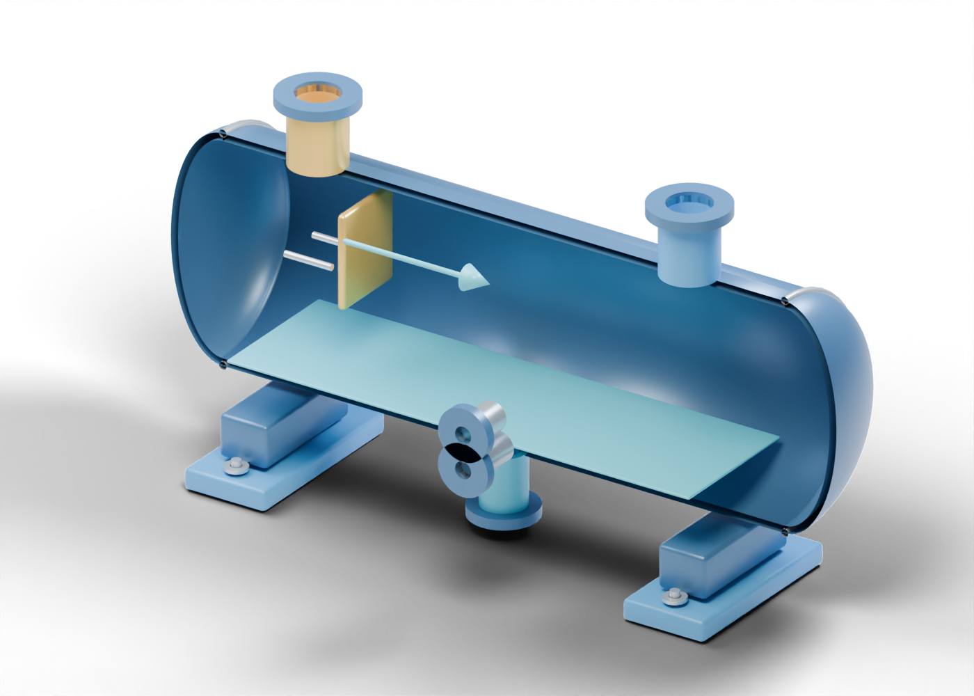
1. Locate the drum in a larger flare system
A knock-out drum is a liquid-removal stage that may sit between a collection header and downstream flare equipment. The U.S. EPA flare chapter describes knock-out drums separately from liquid seals, flare stacks and other system components. It distinguishes horizontal and vertical vessel arrangements. That context explains a role; it does not size or approve this original illustration.
The Alberta Energy Regulator's Directive 060 covers upstream flaring, incinerating and venting in Alberta. Its current source page was checked on 27 September 2026. Our original 34-part 3D teaching model is not a Directive 060 design, permit, compliance finding or named Alberta facility. The blue vessel, gold inlet marker and light-blue liquid region are original presentation choices, not an industry colour code.
2. Follow five actual geometric openings
The intact 3D vessel has a hollow shell with five real wall bores. Separate open necks and bored collars mark the header inlet, gas outlet, lower liquid outlet and two level-instrument boundaries. The illustrated openings and adjacent wall regions do not establish a pressure boundary or compliant vessel. The shell and both closures remain intact in the 3D file; only the poster removes its facing half to expose the interior.
The inlet and outlet are boundaries of this single vessel model, not connected pipework. The two smaller side connections show where level instrumentation might be discussed, without supplying a gauge, control logic or setpoint. The lower outlet does not show a pump, storage tank, treatment or disposal route.
3. Read the internal markers without inventing performance
The gold plate near the inlet is an independent impact-location marker. Three small standoffs make its separation from the shell inspectable. The pale blue sheet is an arbitrary static teaching plane, not fluid simulation, a measured level or a calculated surge volume. No droplet trajectory, residence time or separation efficiency is represented. The base feet have four actual anchor-location openings, but no loads or foundation design.
| Original model element | Inspectable evidence | Still outside the model |
|---|---|---|
| Header inlet and gas outlet | Distinct drilled shell paths and hollow collars | Actual header, seal, stack and gas composition |
| Inlet impact plate | Separate solid visual marker | Selected baffle design or liquid-removal result |
| Blue lower region | Colour boundary inside the cutaway | Liquid volume, live level or surge-capacity calculation |
| Lower liquid neck | Real open shell passage | Pumping, storage, treatment and safe disposal |
| Two side boundaries | Separate openings at different heights | Instruments, alarms, controls or protective settings |
4. Keep the drum separate from the rest of the flare
A knock-out drum alone cannot establish complete flare-system performance. The EPA chapter treats the liquid seal and flare stack as distinct components. This scene has neither, and it has no pilot, purge, relief header, combustion, emissions measurement or verified liquid handling. A blue gas arrow sits outside the vessel solely to help read the drawing; it is not a flow simulation. The horizontal arrangement is an invented example, not a claim that it is appropriate for a particular duty.
5. Ask what supports a real project claim
When a news release says a flare project reduces emissions or improves safety, look for its named site, dated regulatory record, scope, equipment list, operating and measurement basis, and stated result with units. A picture of one vessel does not prove a full system was built, sized or permitted. A design estimate, commissioning record and measured operating result should be distinguished. This educational guide supplies no equipment selection, installation, operation, emergency response or maintenance instruction.
6. Open the original 3D components
Inspect the complete knock-out drum, then focus the header inlet, inlet impact marker, hollow shell, gas outlet, liquid collection outlet, upper level boundary and blue teaching region. These component links identify the original model's parts; they do not endorse a device or installation.