1. Why a stock tank has a vapour question
Crude oil can still contain lighter hydrocarbons after upstream separation. Some enter the headspace of a stock tank as pressure, liquid level and temperature change. The U.S. EPA Natural Gas STAR overview describes flash, working and standing vapour losses in its production-tank example. Those are categories to investigate, not an emissions estimate for any particular Alberta tank.
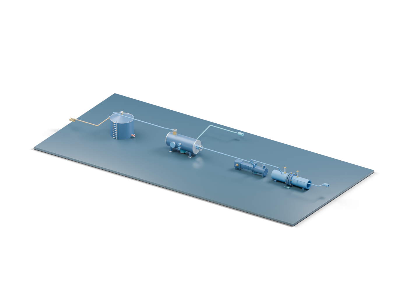
In the connected 3D lesson, the stock-tank wall provides the storage context. The vent connection marks a vapour boundary. It is not a complete pressure-vacuum protection system, a measured vent rate or a connection to a surveyed facility.
2. Follow vapour to liquid removal
The tank-to-scrubber route is a visual relationship between two independently illustrated machines. In the EPA example, tank vapours first enter a suction scrubber where condensed liquid can be collected before the gas reaches a compressor.
Inspect the scrubber inlet collar and hollow vessel. The separate liquid draw ends at an open handling boundary. Real liquid return, storage or disposal depends on a site-specific system; none is designed by this drawing.
3. Compression is a role, not a selected package
The EPA's illustrated example sends scrubbed vapour through an electrically driven rotary compressor. Our compressor model is a separately authored reciprocating machine placed here to explain a compression role. It does not reproduce the EPA package or show that these particular pieces of equipment fit together.
The scrubber-to-compressor route does not specify suction pressure, capacity, controls, tank-vacuum protection, relief, power or safe operation. A project announcement that says it added vapour recovery should identify what was actually installed and commissioned.
4. A meter location is not a gas-quality result
The scene places an independent orifice-meter-run illustration after the compression role. The EPA example describes metering before recovered gas goes to further handling, which may include suitable onsite fuel use or sale. Our line ends at an open gas boundary. No gas composition, metered volume, acceptance test or downstream destination is supplied.
| Illustrated element | Useful question | What the picture cannot prove |
|---|---|---|
| Stock-tank vent location | Where is the vapour boundary? | An actual vent rate or pressure protection |
| Suction scrubber | Where could liquid be removed? | Removal efficiency or compressor-feed suitability |
| Compressor role | Why might pressure need to change? | Selected capacity, controls or compatible equipment |
| Meter location | Where might gas quantity be checked? | Calibrated volume or saleable-gas quality |
| Open liquid and gas exits | Where does this lesson stop? | A complete handling, emissions or disposal system |
5. Read recovery and emissions claims carefully
A model can show where a recovery system might connect. It cannot demonstrate captured volume or emissions reduction. For a real project, distinguish a proposed unit from installed equipment and commissioned operation. Ask what tank or tanks are included, what period the claim covers, how vapour generation and recovered gas were measured or estimated, where liquids and gas went, and what evidence supports the result.
The historical EPA report explains one general approach; its example performance and economics are not a current Alberta forecast. Tank controls, hazardous-area electrical work, relief, maintenance and regulatory requirements need qualified site-specific assessment. This article is a reading aid for news coverage, not a design or operating procedure.
6. Explore the separate lessons
Open the full connected 3D scene to select parts and compare the labelled vapour, liquid and oil relationships. The oil-battery explainer covers separation, treatment and storage before this question arises. The suction-scrubber explainer focuses on liquid removal, and the orifice-meter explainer shows why a visible restriction is not a validated flow reading. Each model is independent; together they form a learning path, not a matched plant.