1. Why put a scrubber ahead of compression?
A compressor suction scrubber is a gas-handling vessel used to separate residual liquid from a stream before it reaches compression. SLB's gas-scrubber technical paper discusses liquid-removal roles in compressor and gas-treatment service. An Emerson application note describes scrubber bottles used to protect compressors from residual fluid and explains why real systems may need level detection and liquid dumping. These references establish broad roles; they do not describe or approve the drawing below.
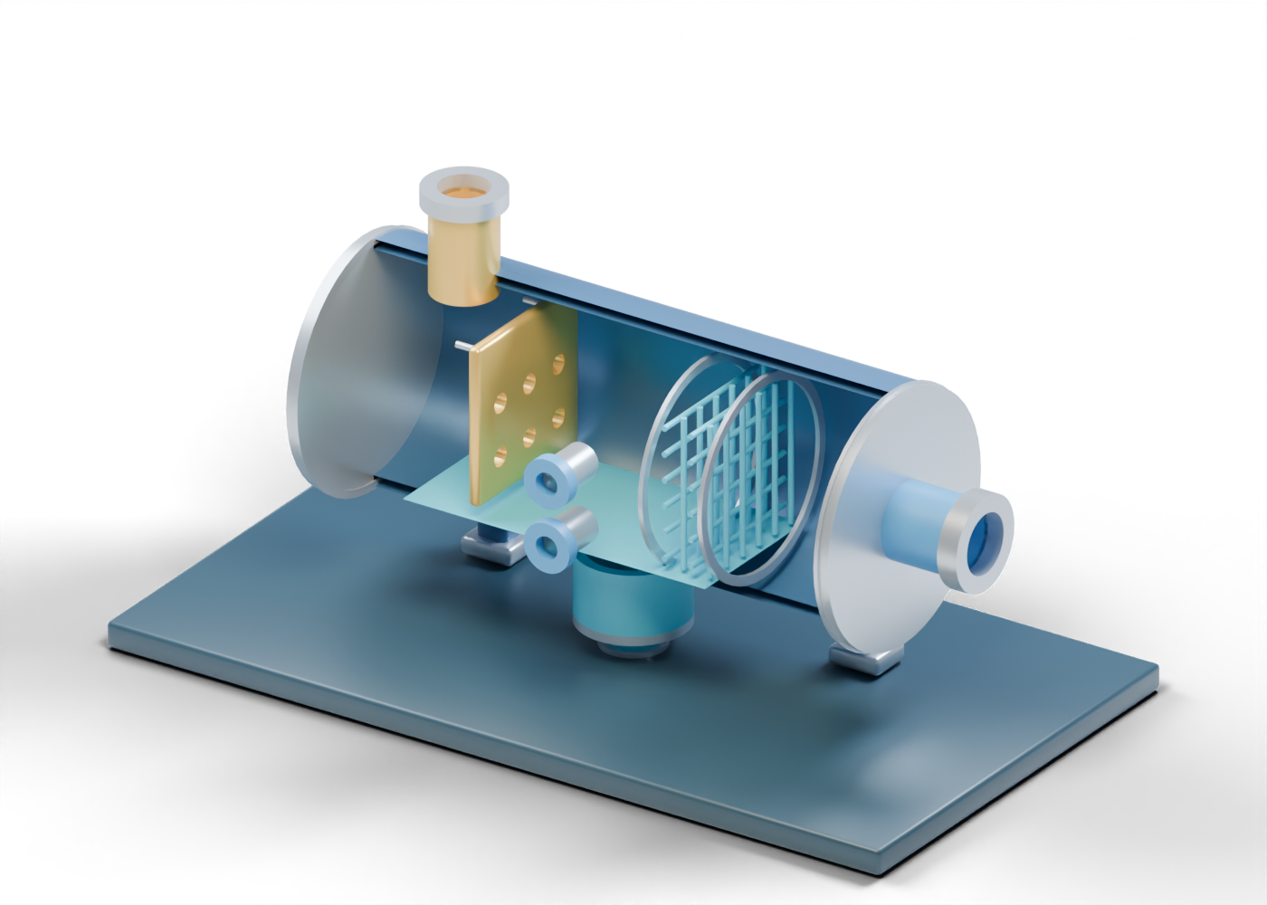
Our original horizontal 3D scrubber lesson shows one invented teaching arrangement. It is not a named Alberta facility, a vendor product, or a specification for a compressor package. AlbertaOil's interactive model keeps the full enclosure and closed inspection cover; the blue-and-gold poster opens only the facing half so the component locations can be read.
2. Start at the actual inlet opening
The mixed-gas inlet meets a real bore in the complete shell. Incoming gas could carry liquid, but the 3D file contains no fluid sample, velocity or loading data. The separate perforated diversion plate has six real holes. It points out where an inlet-diversion function might be considered; its invented size and position do not predict liquid removal or flow distribution.
The model's left end is closed. The right end has a bored gas exit. A sectioned illustration can help identify the distinction between a vessel wall, an internal marker and an external connection, but it cannot establish pressure integrity or a sealed route between them.
3. Read the mist region without assigning a rating
Two annular retainers frame 24 independent, open mist-weave strands. This makes a later mist-removal location visible and selectable. It is not a drawing of specified mesh, a vendor pad, a filter element or a tested demister. Real selection depends on the gas, droplets, pressure, temperature, liquid loading, allowable pressure loss and the project's downstream requirement.
| 3D element | Helps locate | Does not prove |
|---|---|---|
| Mixed-gas inlet | Arrival boundary | Feed composition or pressure rating |
| Six-hole plate | Possible diversion location | Bulk-liquid capture or distribution |
| Open mist weave | Later mist-removal region | Media specification or efficiency |
| Lower liquid boot | Separate collection location | Capacity or actual liquid level |
| Compressor-side gas exit | Gas destination | Dry-gas guarantee or compressor protection |
4. Keep liquid handling distinct from gas exit
The hollow lower boot connects to a real opening in the vessel floor, and its lower closure has a separate bore leading to the open liquid drain. The blue static plane is an arbitrary location cue, not a level reading. The upper observation opening and lower observation opening are uninstrumented locations only. They are not a gauge, alarm, control loop or setpoint.
In a real package, level detection, a dump valve, downstream liquid handling and compressor protection need a coordinated design. The Emerson note describes why those functions matter. This illustration intentionally stops at the open boundaries and cannot suggest an operating sequence or confirm an interlock.
5. Compare neighbouring equipment by role
A vertical filter separator can illustrate distinct cartridge and mist stages in gas treatment. A gas-liquid coalescer focuses on droplet-removal concepts. A finger-style slug catcher illustrates temporary handling of larger incoming liquid volumes at a facility inlet. These drawings are independent learning objects, not one connected or compatible plant.
When a project claims improved compressor reliability or gas quality, ask for the actual inlet and outlet measurements, the time period, liquid-loading basis, pad or element specification, pressure-drop data and compressor requirements. A polished render cannot verify those results.
6. Inspect the complete model
Open the scrubber inside AlbertaOil's equipment atlas, then select the inlet, six-hole plate, mist-region strand, gas exit, liquid boot and drain. The interactive 59-part model also lets you inspect the closed inspection cover. Neither the 3D view nor this guide is an equipment design, maintenance procedure or safety instruction.