1. Begin with the plate, not a number
An orifice plate is a restriction placed in a full conduit so a pressure difference can be used as part of a flow-measurement method. ASME's scope for differential-pressure devices explicitly concerns the device geometry, installation and flowing conditions. Emerson's orifice-plate overview describes the plate as a primary element within broader differential-pressure measurement. Neither source supplies a calibration or approval for our drawing.
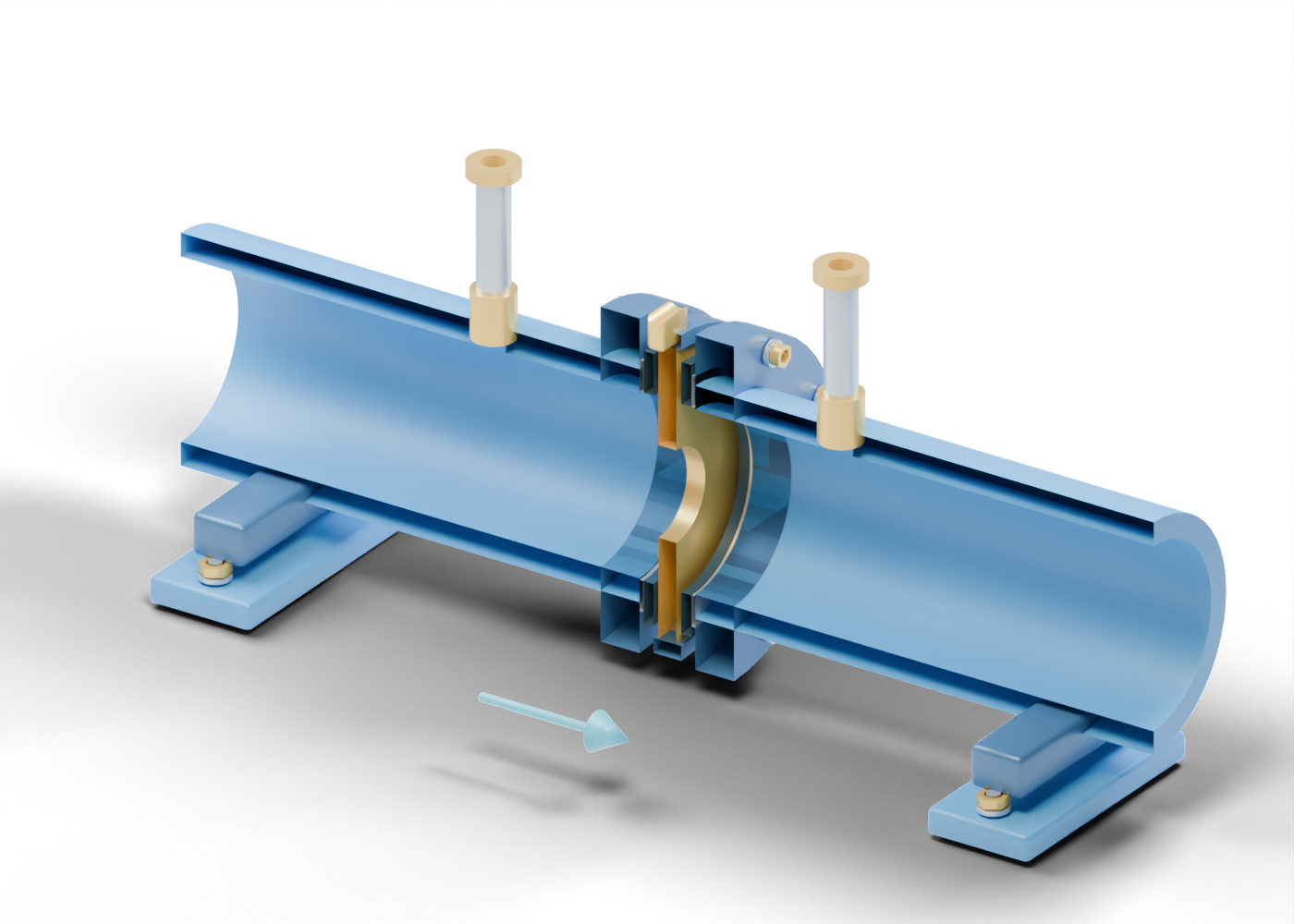
Our original 75-part 3D meter-run cutaway has an open upstream tube, a separate thin plate with a real smaller central aperture, and an open downstream tube. Alberta blue distinguishes the pipe, prairie gold the plate and tap collars, and steel the joint locations. The interactive model retains the tube walls; the still hides the facing half to show the restriction. No OEM CAD, published diagram, dimensions, standard plate profile or named Alberta installation was imported.
2. Trace two geometric pressure paths
One drilled opening passes through the upstream pipe wall; a second passes through the downstream wall. Each reaches its own hollow neck and vertical open line envelope. The upper collars end at the scene boundary. There is no transmitter, measured differential or signal in the model. The plate aperture is real geometry, but a rendered gap does not measure flow.
The plate's annular wall remains visible around its opening. Two distinct gasket-location rings flank it, and a hollow carrier outline surrounds it. The gaskets are not compressed; the carrier does not establish a retention design or safe access method. The flange bores, smooth studs, bored nuts and washers show separate component locations, not a selected pressure-rated joint.
3. Compare what this and a Venturi show
The separate AlbertaOil Venturi 3D model provides a geometry comparison. Its invented passage narrows gradually to a throat and then expands; this orifice scene uses a separate restrictive plate. Both expose two independent pressure locations. Neither shows a fluid simulation, connected measurement chain or calibrated flow reading. The models are separate teaching objects and should not be treated as alternative qualified products for one duty.
4. Separate the visible evidence from metering evidence
| Part of the original scene | What can be inspected | What a real measurement claim needs |
|---|---|---|
| Upstream and downstream open tubes | Distinct full-size internal pipe boundaries | Actual pipe geometry, full-pipe conditions and installation record |
| Gold restriction plate | A smaller real aperture and retained annular material | Selected plate profile, diameter ratio, condition and traceability |
| Two wall taps and open line collars | Independent drilled geometric paths | Pressure readings, impulse connections and instrument records |
| Gasket, carrier and flanges | Separate location markers and bored joint parts | Suitable materials, rated fit, containment and inspection evidence |
| Supports and direction arrow | Invented placement and static reading direction | Actual flow direction, support design and site survey |
The fresh exported-GLB readback checked five clear selected axial rays through the aperture, a retained plate-wall ray, the two pressure paths, 43 selected component openings and 20 washer holes. That is evidence about selected illustration geometry, not about measurement accuracy, pressure containment, a standard-conforming plate or complete collision clearance.
5. Read a project metering claim carefully
If a story says a new meter improved reporting or custody transfer, ask for the named site and meter, the date, measured quantities and units, instrument and calculation records, operating range, uncertainty basis and the source of the comparison. A plate photograph shows appearance at one moment; it does not by itself show calibration, installed straight lengths, flowing gas properties or an audited volume. A quoted capacity, a design estimate and a measured result should remain separate.
This original guide supplies no selection, installation, calibration, operating or maintenance instruction. Equipment illustrations cannot replace current project documents, applicable standards and qualified metrology work.
6. Explore exact 3D parts
Open the complete orifice meter-run for ten guided stops and a full 3D inspector. Focus the restriction plate, upstream tube, upstream tap, downstream tap, upstream flange and downstream tube.
Compare the Bourdon gauge guide to distinguish a pressure indication concept from a flow primary element. The two independent models do not form an installed measurement system.