1. Look behind the pointer
The face of a gauge presents a reading. Behind it, a sensing element and a movement connect a physical response to the pointer. WIKA describes a C-shaped tube with an oval cross-section: internal pressure changes its shape, its free end moves, and a movement transfers that displacement to a pointer. Its undated explanation is a source for this general principle. WIKA: Bourdon-tube operating principle.
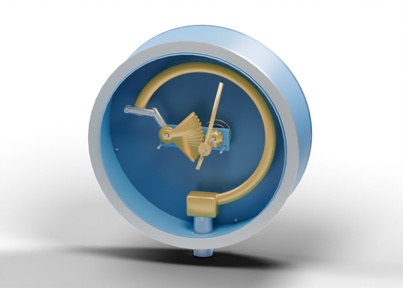
Our original 3D model makes those regions inspectable through 89 individually named mesh instances. A blue case surrounds a gold curved tube, silver linkage and separate movement parts. Twelve guided studies connect names to visible features. The model has invented proportions and a static pointer; it does not calculate the physical response described by WIKA.
2. Trace the pressure-entry geometry
Start with the smooth connection stem at the bottom. Its actual central opening reaches a vertical blind passage in the fixed socket. A lateral gallery meets that passage and reaches the curved tube. The socket retains material at its upper and left ends.
The C-shaped tube has distinct inner and outer oval surfaces. The lumen follows its curved centreline to a separate solid tip marker. The open entry and closed free-end location are different parts of the drawing, rather than an uninterrupted solid rod.
The illustrated tube follows an oval path, without a measured pressure-response curve. Selected rays also checked the entry galleries and retained walls. These are geometric features only. They do not establish leak-tight joints, a pressure rating or a selected connection.
3. Follow the movement as separate parts
An external lug marks the tube-tip link location. A rounded-end link, separate pivot markers and a lever lead to a partial gear-shaped member. A smaller pinion-shaped member surrounds the pointer spindle. Front and rear bridges, separate bushes and smooth joint hardware distinguish the support regions. A spiral strip marks a spring location behind the movement.
The fourteen sector teeth and twelve pinion teeth are invented radial envelopes. Their counts do not establish a gear ratio or correct tooth engagement. Deliberate gaps make members easier to identify. There is no gear motion, calibrated travel, spring-force or tube-deflection calculation.
In the illustration, the dial, its ticks and the front bridge are omitted to expose these internal regions. The interactive model retains them. The illustration is a presentation view, not a sequence for opening an instrument.
4. Keep a visible pointer separate from a measured value
| Region in this original model | What the drawing establishes | Evidence it does not supply |
|---|---|---|
| Connection stem and fixed socket | Open stem and connected blind gallery locations | Selected fitting, installation, pressure rating or leakage result |
| Curved oval tube and tip | Separate inner/outer surfaces and closed-tip marker | Elastic response, stress, hysteresis or measured pressure |
| Link, lever, sector and pinion | Individually inspectable static movement regions | Qualified tooth contact, gear ratio, calibrated travel or friction |
| Bridges, bushes and spiral marker | Separate support and spring-location regions | Selected fit, restoring force, spring rate or durability |
| Plain dial, ticks and pointer | Forty-one unitless tick positions and an arbitrary pointer pose | Units, calibrated range, accuracy, reference pressure or a reading |
| Case, cover and window-location ring | Separate enclosure surfaces and openings | Glass, ingress or safety classification and service suitability |
The dial carries no numbers or units. Moving the camera or selecting a part does not turn the static pointer into a measurement. The original model also supplies no electrical signal, alarm or process-control result.
5. Read pressure-related news with its evidence attached
A reported pressure value needs enough context for a reader to understand what was measured. Look for the named asset and location, time of observation, stated units, measurement source and the source's own explanation of the pressure reference. Keep an indicated value, a manufacturer's rating and a stated alarm or relief setting distinct in your notes.
For an instrument replacement or reliability story, identify the claimed change and the evidence attached to it. A photograph can establish visible features in that photograph; it does not by itself establish calibration, a before-and-after comparison or improved plant performance. Missing evidence should remain identified as missing rather than filled in from this teaching model.
This guide reports no actual plant reading or incident. It explains the original drawing and provides questions for reading source material. It supplies no selection, installation, calibration, operation or maintenance instruction.
6. Explore the tube and compare component roles
Open the Bourdon pressure gauge for the intact assembly. Follow the hollow oval tube, fixed pressure socket and uncalibrated dial as exact named components.
Compare the control, isolation and check-valve guide, pressure-relief guide and three-phase separation guide. These separate examples help distinguish indication, flow-control, relief and separation vocabulary. They do not specify a connected installation, a compatible instrument or a protection system.