1. Begin with “free water”
Free water can settle from a produced mixture more readily than water held in a tight oil emulsion. Kimray’s FWKO training describes removal before further treatment; the SLB glossary notes that “free-water knockout” and “three-phase separator” can be overlapping names. A headline about water removed still needs to specify which water, at what process boundary, and how the result was measured.
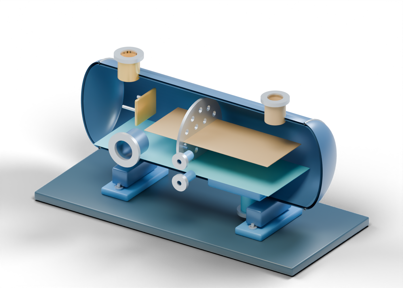
Our original 3D cutaway chooses an unheated two-phase teaching arrangement. Its lower water draw is separate from the combined oil-and-gas emulsion exit. It is not a depiction of a named Alberta facility or copied equipment.
2. Read the boundaries before the interior
The mixed-feed opening leads into a complete horizontal enclosure. A separate impact plate marks a possible inlet-diversion location. Its form and spacing are invented, not a tested duty.
The oil-and-gas emulsion exit deliberately keeps those remaining streams together in this two-phase example. The free-water draw leaves from the lower region. None of these geometric openings includes a selected valve, instrument, rated connection or downstream line.
3. Look through the quieting location
The quieting-baffle marker contains nineteen actual geometric holes. Kimray describes this as one possible internal role; our count and pattern are invented for inspection. Holes in a render are not a residence-time calculation, emulsion test or proof of water removal.
Two static planes help distinguish a lower water region from an upper emulsion marker. Their heights are arbitrary, so they cannot report a live interface. The open-spaced water-pocket rail suggests a lower collecting zone; it is not a sealed water box.
| 3D element | Helps locate | Does not prove |
|---|---|---|
| Feed neck and impact marker | Entrance and diversion location | Feed composition or momentum reduction |
| Nineteen-hole plate | Possible quieting zone | Chosen hole design or residence time |
| Blue lower plane | Free-water region | Interface level or water cut |
| Lower draw | Destination separate from emulsion | Dump-valve action or water-handling permission |
| Upper emulsion exit | Need for further processing | Oil or gas sales readiness |
4. Separate level locations from controls
The lower interface neck and upper liquid neck are drilled locations, not gauges. Kimray’s general explanation mentions controllers and dump valves in actual arrangements. This scene has no float, transmitter, setpoint or valve sequence, and gives no operating instruction.
The inspection cover is solid and closed in the browser model. Only the poster removes a facing enclosure half. The drawing is not a vessel-entry, isolation or maintenance procedure.
5. Compare the wider separation story
Our separate three-phase separator lesson shows gas, oil and water outlets as distinct teaching boundaries. The two models use different simplified layouts; neither shows a matched train or a universal equipment choice. ATLAS Oil & Gas Process Systems in Nisku describes custom vessels that vary with field conditions.
For a project claim about improved water handling, look for inlet and outlet basis, sampling period, fluid properties and downstream treatment. Artwork alone cannot establish corrosion reduction, emulsion breakup, disposal permission, pressure safety, emissions or production gains.
6. Explore exact parts
In the 3D model, reveal the internals, isolate the perforated plate and compare the water draw with the emulsion exit. Its 43 named parts, six shell openings and nineteen plate holes are original teaching geometry, not process evidence.