1. Start before the flare equipment
A flare-system drawing begins somewhere, but an open line does not tell you which process equipment, relief device or vent source supplies it. The historical U.S. EPA OAQPS flare process description identifies a gas-collection header, a liquid knock-out drum, a possible separate liquid seal, and an elevated stack and tip as common roles. It is a general reference, not a current specification for an Alberta site.
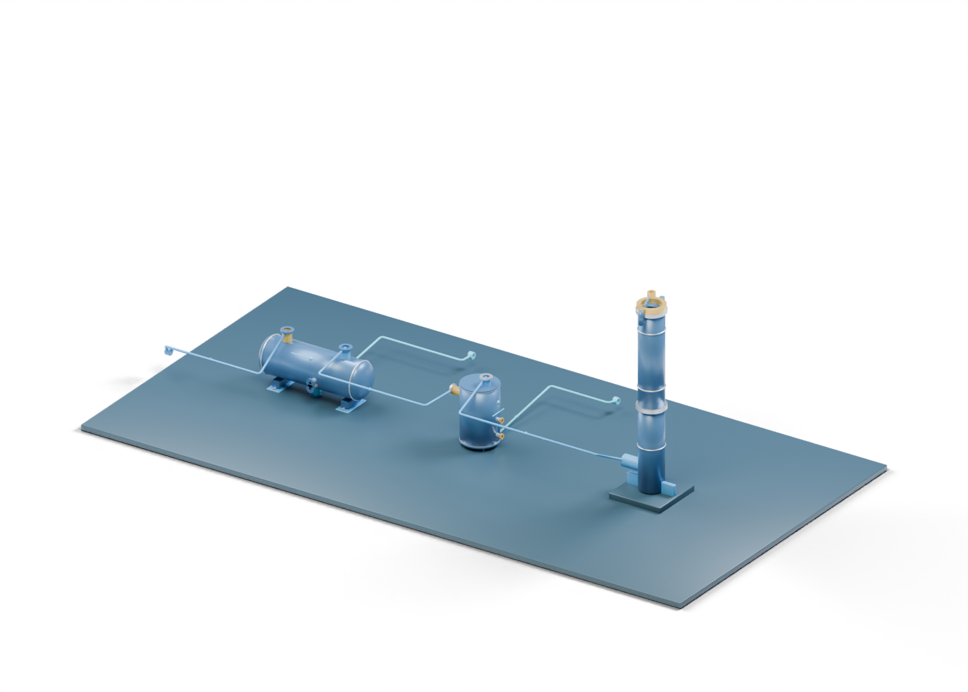
The open upstream boundary in the connected 3D lesson intentionally stops before real collection and protection details. Follow the header-to-drum route as a static reading cue. The model does not establish relief capacity, line sizing, backpressure, routing or a safe operating state.
2. Ask what happens to liquid
The EPA description says liquids in a vent stream or condensed along transfer lines may be removed ahead of the stack. In our scene, the separately authored hollow knock-out drum has visible inlet, gas and liquid boundaries. The liquid collection collar leads toward an open liquid-handling edge. A real project must identify where that liquid goes and how the vessel is designed for its service. No separation efficiency, capacity or upset case can be read from a shape.
3. Treat the seal as an illustrated role
The EPA reference describes a liquid seal that may follow the knock-out drum or be incorporated elsewhere. Our independent bent inlet and submerged leg and static liquid surface make that relationship visible. The separate gas outlet collar points toward the stack. None of these parts proves a maintained seal height, purge arrangement, flashback prevention, pressure behaviour or compatible installation.
4. Look up the hollow stack
The scene adds a newly authored hollow lower stack barrel with a real side opening, a separate upper barrel and an open tip location. The small pilot-position envelopes are markers only; there is no functional pilot, ignition, flame or gas seal. At the open boundary above the tip, the teaching geometry ends. The drawing says nothing about stack height selection, combustion efficiency, plume, noise or measured emissions.
| Illustrated element | Useful question | What the picture cannot prove |
|---|---|---|
| Open incoming header boundary | What source and relief path would feed this system? | A complete or correctly sized collection network |
| Knock-out drum | Where might liquid be removed? | Removal efficiency or upset capacity |
| Separate liquid-seal role | What is the relationship to the gas path? | A functioning seal or flashback protection |
| Hollow stack and open tip | Where does the gas path rise? | Ignition, flame stability or structural design |
| Open liquid and atmospheric exits | Where does the lesson stop? | Liquid disposition, combustion or emissions results |
5. Read flare claims as evidence questions
A project report may say a flare was installed, operated, improved or reduced emissions. Those are different claims. Ask which equipment was actually installed and commissioned, what gas sources and operating period were covered, whether the pilot and monitoring were functioning, how gas quantity and composition were determined, what happened to collected liquids, and which measured or documented basis supports any emissions statement. A static model answers none of those questions. Local permit, safety and operating requirements need site-specific qualified assessment.
6. Continue through the separate models
Use the full connected 3D scene to select parts and compare the gas and liquid paths. The knock-out drum guide examines the hollow vessel and its liquid outlet; the liquid-seal guide explains why a static blue plane is not proof of protection. The tank-vapour recovery guide covers a different question: recovering vapour from a stock tank for further handling. These illustrations are independent teaching aids, not selected equipment for one plant.