1. Why separate sand near a wellhead?
Produced sand can threaten downstream production equipment. SLB's wellhead desander overview explains the broad role of removing sand from wellhead fluids before later equipment. NOV's wellhead cyclonics sheet describes a lower solids-accumulation location in a wellhead separation system. These sources inform the vocabulary, not the design of this illustration. No vendor CAD, art, dimensions or performance figures were copied.
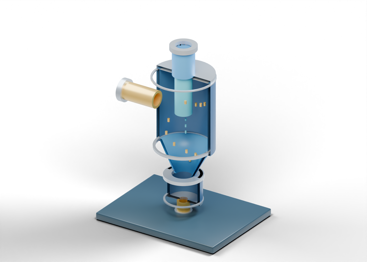
The original AlbertaOil sand-separator lesson has 51 selectable parts in a blue-and-prairie-gold 3D scene. Its poster sections facing walls so the separate roles can be read. The interactive model retains the complete upper barrel, cone and lower pot. It represents no installed well or selected product.
2. Enter the upper vessel
The offset open feed reaches a real opening in the complete upper barrel. The feed's placement suggests where arrival could be discussed, but its offset does not prove tangential flow or a chosen cyclone inlet. A separate open feed collar marks the external boundary. There is no specified wellstream, flow rate, pressure or sand loading.
The closed barrel inspection cover sits over a different actual wall opening. It stays closed in the full 3D model. Neither the poster nor the part inspector gives an isolation or vessel-entry procedure.
3. Read the two possible paths
A central overflow-reading tube points toward an upper produced-fluid outlet through a real bore in the top closure. The tube is a location cue for the lighter stream, not proof of a vortex, solids-free fluid or downstream suitability. Eight small blue central path markers are fixed, not a flow animation.
Twelve gold marks, including descending marker 6, help locate a possible downward solids route. They are not grains, measured trajectories or a separation calculation. Actual sand capture depends on a qualified design and operating conditions absent from this scene.
| Teaching element | Helps locate | Does not establish |
|---|---|---|
| Offset open feed | Arrival into the upper barrel | Selected inlet or tangential flow |
| Central overflow cue | Possible lighter-stream destination | Clean-fluid quality or vortex behaviour |
| Fixed gold and blue markers | Two conceptual reading routes | Particle trajectories or capture efficiency |
| Open cone and lower pot | Possible solids collection region | Accumulation capacity or pressure rating |
| Lower open boundary | Further sand handling | Valve sequence, isolation or disposal approval |
4. Inspect the cone and collection pot
The complete open conical transition has separate inner and outer surfaces and open ends. Its proportions are invented. The hollow lower pot is a distinct enclosure below it, with a separate closed access cover. The cone-to-pot ring marks proximity rather than a verified sealed joint.
A real vessel needs project-specific mechanical design, materials, corrosion and erosion review, instrumentation and a plan for collected solids. A visual cone or pot cannot establish any of those outcomes.
5. Keep solids handling separate
The pot's lower closure has a real opening into a sand-removal boundary. Its open end collar stops before any valve or downstream handling. The illustration deliberately gives no drain, isolation, depressurization or disposal instruction. The closed pot inspection cover is likewise an access-location cue, not permission to open equipment.
Compare the free-water knockout for a different liquid-removal question, and the compressor suction scrubber for gas/liquid protection before compression. These separate original models do not form a matched process train.
6. Explore the complete 3D lesson
Open AlbertaOil's interactive sand-separator page and select the feed, barrel, central outlet cue, cone, lower pot and sand boundary. Toggle the half-section to see the static roles. The complete model remains a teaching illustration, not a fabrication drawing, separation guarantee, operating procedure or safety instruction.