1. Read the two-well relationship
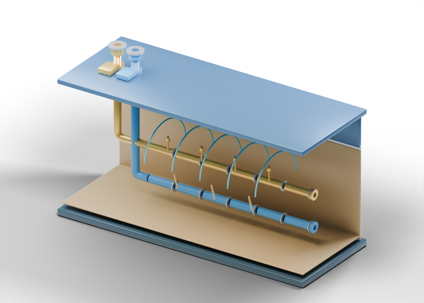
Steam-assisted gravity drainage (SAGD) is an in-situ oil-sands method. The Alberta Geological Survey's oil-sands overview describes an upper horizontal well that injects steam and a lower horizontal well that produces heated bitumen and condensed water. The Alberta Energy Regulator glossary makes the same injector–producer distinction. That is the relationship illustrated here; the well paths do not depict a named field or a surveyed pad.
Our drawing separates the upper gold injector path from the lower blue producer path so both can be inspected. Each ends at its own open surface boundary. The separation on screen is for reading the roles; it is not a drilling plan, required spacing or reservoir depth.
2. Follow the open paths
Select the Injector curved well path and Producer curved well path. Both are hollow paths that turn from a surface location into a horizontal direction. Their independent endpoints make it easier to see that injection and production have different jobs. Open liner pieces further along each path are visual sections, with gaps that expose their ends. Those gaps are not chosen perforations, slots or a steam-distribution design.
| What the illustration shows | What it helps explain | What it cannot establish |
|---|---|---|
| Upper injector path | Steam enters through an upper well role | Injection pressure, rate or completion |
| Lower producer path | Produced fluids return through a lower well role | Inflow, lift method or production rate |
| Open surface collars | The two paths have separate external boundaries | Wellhead equipment or connected facilities |
| Separate liner sections | Each horizontal path can be inspected in 3D | Screen, perforation or joint specification |
| Reservoir backplane | The paths sit within a visual subsurface section | Mapped geology or pay thickness |
3. Interpret the chamber outline
The blue arches mark a conceptual heated region above the injector. They are separate open outlines, not a filled steam volume or a measured chamber. Gold upward arrows and brown downward markers explain the direction of the teaching story: steam heats bitumen, and mobile fluids can drain toward the lower producer. They do not calculate temperature, viscosity, chamber growth, containment, water use or recovery.
The model's ground surface has two geometric openings and a backplane behind the wells. Those shapes make the scene readable; they do not represent well integrity, actual rock properties or the position of a geological boundary. The AGS page explains the general SAGD mechanism, not the conditions at a particular project.
4. Keep the surface plant separate
Steam generation and treatment are substantial parts of a real in-situ project, but this scene stops at the two well boundaries. To inspect the separate steam-generation role, open the once-through steam-generator cutaway. Produced fluids would also require surface handling and separation. An equipment category seen elsewhere in our library, such as a three-phase separator, can teach a general separation role; it is a separate concept and has not been matched to these wells. This well-pair illustration offers no heat balance, steam generator, water-recycling system, emissions estimate or facility layout.
5. Ask better questions of a project headline
When an Alberta report mentions a SAGD expansion, distinguish a planned well pair from drilled wells, an operating injection program and measured production. Ask which date and project stage the claim covers. If the story reports a steam–oil ratio, water-recycling figure or recovery expectation, look for the reporting period, units, definitions and site-specific source. The shape of a teaching arch cannot validate those results.
The same distinction matters for regulatory or environmental claims. AER's glossary defines the method; it does not approve this drawing as a well design or verify any operator's performance. A project-specific conclusion needs current records and qualified review.
6. Inspect the 3D lesson
Open the complete SAGD well-pair scene. Trace the Injector open boundary collar, Injector open liner section 3, Steam-chamber outline 3, Illustrative upward steam marker 2, Illustrative gravity-drainage marker 2, Producer open liner section 3 and Producer open boundary collar. Then compare the separate three-phase separator lesson for a general surface-processing role. These models do not form a designed or operating plant.