1. Start with the two different duties
Glycol dehydration removes water from a natural-gas stream in a gas contactor. Regeneration reconcentrates the glycol that has taken up water so the solvent can return. These are related but distinct duties. The historical U.S. EPA/GRI glycol-dehydrator study gives a general absorber/regenerator process overview and shows an optional flash tank. SLB's glycol systems overview describes the broad rich-to-lean reconcentration relationship. Neither source supplies an Alberta facility survey or validates our artwork.
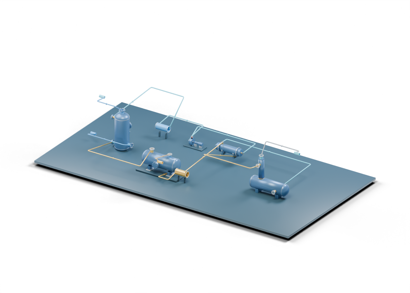
This 802-part original 3D scene uses five independently authored models: a gas/glycol contactor, optional flash tank, still and reboiler, shell-and-tube exchanger and centrifugal pump. Two much simpler hollow envelopes mark a filter and cooler role. The equipment was rescaled for one readable picture; the shapes are not a compatible equipment package.
2. Follow the gas and rich-glycol sides
The blue wet-gas line ends at the contactor's inlet region. Another blue line leaves its top dry-gas boundary. “Dry” identifies the purpose of the gas outlet; it is not a measured water content, dewpoint or pipeline-quality certificate. The gas paths stop at open scene boundaries. Feed conditioning, gas composition, flow, pressure and actual specification remain outside the model.
Gold lines mark rich glycol leaving the contactor toward the optional flash-tank concept. A separate flash-gas line ends at its own boundary. That line does not show fuel use, recovery, control, a permit or a methane-reduction result. Downstream of the illustrated flash role, gold continues through a schematic filter location and one declared side of the original exchanger before reaching the still/reboiler rich-feed location. The route positions and order are a teaching layout, not fabricated piping or an operating sequence.
3. Return on the lean side
The still/reboiler's separate overhead boundary ends at an open water-vapor marker. No condenser, vent treatment or emissions destination follows it in the scene. The kettle has no burner, heating utility or calculated duty. Cyan lines lead from a lean-glycol outlet through the other declared exchanger side, an original pump concept and a schematic cooler envelope, then back to the upper contactor boundary. They close the educational diagram, not a heat balance, mass balance or measured circulation loop.
The exchanger is a detailed independent shell-and-tube model reused to distinguish two path roles. Its pass arrangement, surfaces, duty and connection sizes were never matched to the glycol vessels. The pump's impeller, shaft and casing are inspectable in its separate model, but the scene supplies no pump curve, driver, seal plan or selected glycol service.
4. Keep the picture and the evidence separate
| Region in the 3D scene | What can be inspected | What a real project must establish |
|---|---|---|
| Contactor and gas boundaries | Distinct feed, outlet and glycol connections | Gas and glycol analyses, drying target, capacity and achieved outlet quality |
| Optional flash-gas branch | Its own open route and vessel boundary | Installed equipment, gas destination, control, measurements and permits |
| Rich-side filter and exchanger roles | Separate position markers and a reused detailed exchanger | Selected internals, filtration result, heat duty and compatible connections |
| Still/reboiler and overhead | Rich feed, lean outlet and water-vapor boundary | Heat source, solvent reconcentration, actual vent handling and protection |
| Pump, cooler and lean return | Conceptual circulation path back to contact | Pump curve, cooling duty, control, flow and operating evidence |
Twelve routes in the model have actual endpoints near their declared source-part centres. That is a consistency check on the illustration. It cannot prove pressure containment, fluid continuity, relief or shutdown coverage, instrument design, corrosion resistance, commissioning or environmental compliance. The source models have invented dimensions, and the two envelopes are schematic.
5. Read an Alberta project announcement carefully
If a release announces a dehydrator, identify whether it describes a proposal, ordered equipment, construction, commissioning or measured operation. Ask which site it names, which equipment is actually installed, and what dated inlet/outlet analyses support any drying claim. A quoted design capacity differs from tested throughput. A diagram of a flash tank differs from evidence that flash gas is captured and handled at that site. An overhead line in our image is deliberately an open boundary, so it cannot substantiate an emissions claim.
For a real facility, evidence also has to cover heat supply, pumps and cooling, instrument/control and protective systems, vent or condenser treatment, materials, inspection and applicable permits. The historical U.S. EPA study is process context, not current Alberta regulatory advice. This original educational scene supplies no design, operating or maintenance procedure.
6. Explore the exact 3D components
Open the connected glycol scene to filter gas, rich glycol, optional flash gas, lean return and overhead routes. Focus the contactor boundary, optional flash branch, rich/lean exchanger, still and reboiler, lean pump and return route. Ten guided stops and eleven role cards provide a reading path without treating it as a safe operating sequence.
Use the separate contactor, optional flash and regeneration guides for deeper parts without assuming they describe one matched installation.