1. Why does a refinery desalt crude?
Crude can carry water-soluble salts, metals and solids into a refinery. A desalter brings wash water into contact with crude, then separates a water-rich stream before further refining. The US EPA petroleum refining effluent study explains this broad role and the need to handle the separated water. A second EPA refining study distinguishes refinery desalting before atmospheric distillation from earlier field separation. Neither document supplies the design of the vessel pictured here.
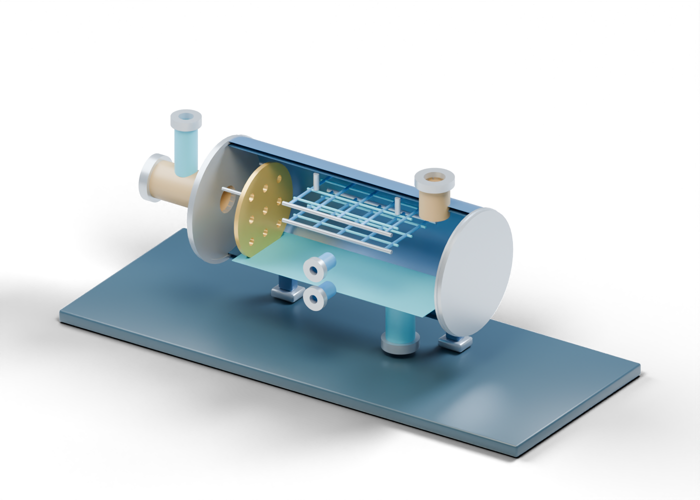
The original AlbertaOil desalter lesson uses a 56-part horizontal teaching scene. The blue and prairie-gold poster opens the near wall for reading; the interactive 3D model retains its complete shell and closed inspection cover. No named refinery, vendor vessel or operating specification is represented.
2. Follow crude and wash water into the same story
Start at the mixed-crude feed, an open tube passing through a bored end closure. The wash-water branch reaches a drilled opening in that feed tube. A separate mix-location marker identifies where their roles meet. It is a location cue, not a mixing valve or a calculation of emulsion formation.
The complete double-surface shell has five actual side openings. Its dimensions, nozzles and closure shapes are invented. A real project must select wash-water quality and quantity, crude conditions, mixing arrangements, vessel code and downstream treatment using project-specific data.
3. Inspect the invented internal markers
A nine-hole inlet plate makes the entry region selectable. The nine bores are real geometry, but their pattern does not establish distribution or separation. Two open lattice decks are assembled from independent rods; select one lattice cross member to see how the model marks a possible electrostatic coalescence region. The rods are not energized electrodes, insulated supports or a manufacturer's design.
| Teaching element | Helps locate | Does not prove |
|---|---|---|
| Crude feed and water branch | Two distinct incoming boundaries | Selected flow, quality or mixing energy |
| Nine-hole entry plate | An inlet-region marker | Actual distribution or salt removal |
| Open lattice decks | A possible coalescence region | Voltage, electric field or efficiency |
| Blue lower plane | A water-region cue | A measured interface or inventory |
| Separate outlet necks | Crude and water destinations | Product or effluent specifications |
4. Keep the two exits and water handling distinct
The upper treated-crude exit is a separate open boundary. Its name does not mean the crude meets a salt specification or is ready for a particular distillation unit. The lower desalter-water exit points to further water handling, not discharge approval. The blue water-region plane is static and arbitrary, not a liquid-level reading. The upper observation opening and lower observation opening are uninstrumented locations; no controller, alarm or setpoint exists in the file.
The EPA sources explain why this water stream matters, but the model cannot show its actual composition or treatment outcome. A useful real-world question is where separated water goes and what measurements demonstrate compliant handling.
5. Compare this refinery role with field separation
A free-water knockout illustrates readily separable produced water in upstream handling. A three-phase separator distinguishes gas, oil and water outlets. This desalter instead focuses on crude washing and a refinery water stream before distillation. Those models are independent lessons, not a connected or compatible plant.
When assessing a claim about a specific desalter, ask for the crude assay, salt measurements before and after treatment, wash-water basis, emulsion behaviour, electrical and pressure design, and water-treatment evidence. None can be inferred from a polished rendering.
6. Inspect the complete model
Open the interactive desalter at AlbertaOil and select the feed, wash-water branch, inlet marker, open lattice, upper crude exit and lower water exit. The closed inspection cover remains closed in the full model. This scene teaches component relationships; it is not equipment design, operating guidance or a maintenance procedure.