1. Place the generator in the SAGD story
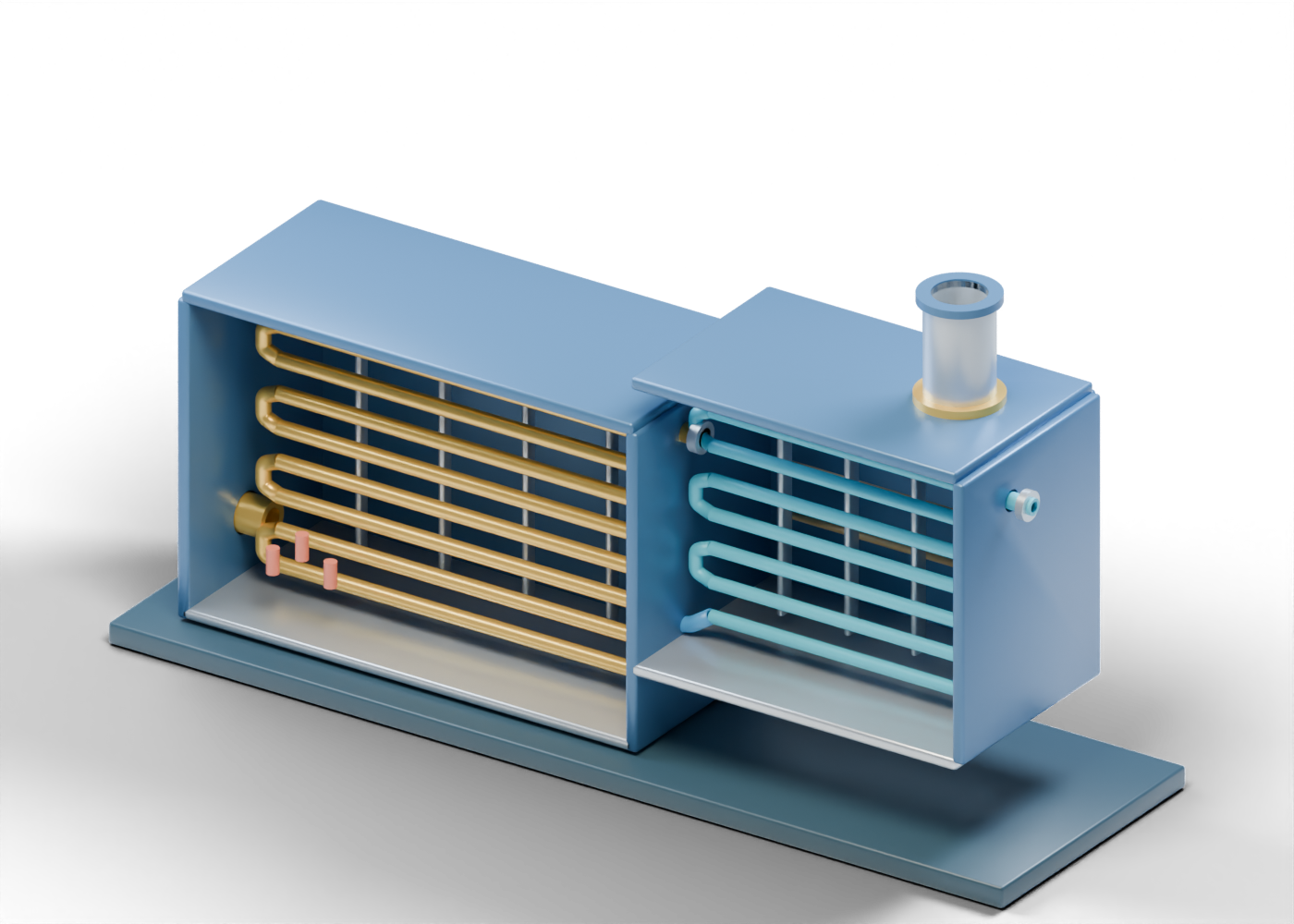
The Government of Alberta oil-sands glossary describes a once-through steam generator (OTSG) as a unit that heats water travelling through tubes. A public Alberta project description illustrates one sequence: preheated feedwater enters a convection section, then a radiant section, before a separate steam separator. Our original 3D cutaway uses those broad roles to organize a lesson. Its housing, tube count, route and proportions are invented; it is not that project's layout or a reference design.
2. Follow the water-side path
Start at the open feedwater inlet. Water source, treatment and feed pumps remain outside this scene. The blue convection tube run 3 is one of seven separate hollow runs. The convection return bend 3 makes the teaching route's change of direction visible.
An open transition path leads to eight gold radiant-section runs. Inspect radiant coil run 4 as a separate hollow part. Blue and gold distinguish the two sections for reading; they do not report temperature, phase, heat transfer or a standard pipe colour.
| In the model | Reader question | What the shape cannot prove |
|---|---|---|
| Feedwater inlet | Where does the water-side path begin? | Water quality, pump capacity or source |
| Convection bank | What is the first heating-section role? | Heat duty, fouling or tube metal temperature |
| Transition | Where does the teaching path change sections? | Constructed routing or a rated connection |
| Radiant bank | Which separate tube group comes next? | Steam quality, pressure or safe service |
| Open outlet | Where does the model stop? | An injection-ready steam system |
3. Separate heating from the water-side path
The open burner register marks a generic heating-side boundary. Small red shapes are static visual markers, not a flame simulation. The open exhaust stack is on that gas side, apart from the water-side outlet. Its shape says nothing about draft, emissions or treatment.
The front of both casings is omitted to expose the tubes. A real project needs separate evidence for casing, insulation, burner controls, fuel supply and safeguards. The cutaway verifies none of those systems.
4. Notice the next process boundary
The open wet-steam outlet path ends at the edge of this model. The cited Alberta project example includes a downstream separator; this cutaway does not design or depict one. A gold tube does not establish steam quality.
The separate SAGD injector and producer well-pair lesson begins at its own open surface boundaries. Comparing the 3D models helps explain roles, but there is no matched pipe, pressure condition, water-treatment train, separator or operating plant between them.
5. Read project claims with their evidence
When an Alberta report mentions steam generation, distinguish proposed capacity, installed equipment and measured operation. Check the project's source, date, units and definition of any steam result. Water recycling, emissions and steam-to-oil figures require site-specific records. Neither a glossary nor an educational model can validate those claims. A generator claim also differs from a well-pair production claim.
6. Inspect the 3D cutaway
Open the complete generator model and trace the feedwater collar, convection run, section transition, radiant return bend, wet-steam outlet and stack. Then inspect the separate SAGD well-pair model for the next conceptual injection role.