1. Begin at the returning fluid
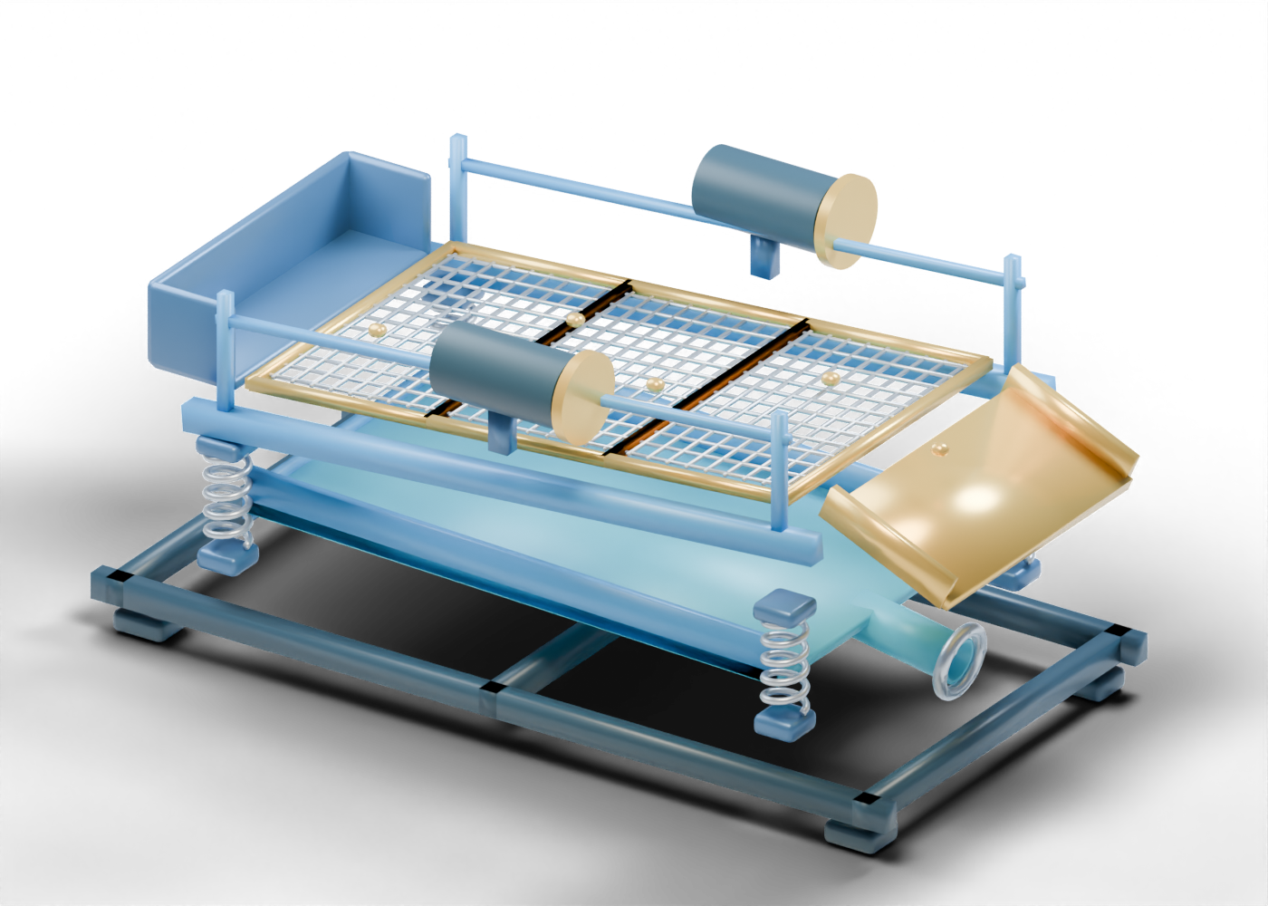
Drilling fluid can bring rock cuttings back from a well. A shale shaker offers an early mechanical solids-control step, while later equipment and waste handling depend on the actual fluid and operation. The SLB solids-control overview distinguishes shakers from centrifuges, cuttings dryers and other equipment. Our original 3D shaker depicts those first screening questions only. Begin at its open mixed-return feed box. The model provides no well, flow rate, mud recipe or rig connection.
2. See the apertures, then question their scale
Select screen panel one, panel two and panel three. Their crossbars are solid geometry and their gaps are real openings in the exported 3D model. The gaps are deliberately large enough to inspect on a phone; they are not a selected wire cloth or API screen designation. NOV describes a real shaker's screen and motion roles, but no NOV layout, patented profile, screen dimension or performance claim is reproduced here. The selectable first panel frame rail is an invented teaching boundary rather than a fit specification.
3. Follow the lower fluid question
Open space beneath the screens leads toward the recovered-fluid tray bottom and bored outlet boundary. These parts show where fluid collection differs from cuttings conveyance. They cannot tell you what solids remain, how much fluid passed, whether the fluid is reusable, or which additional equipment is needed. A real claim about reuse calls for actual fluid analysis and an identified downstream system.
4. Keep the cuttings branch separate
The open cuttings chute is visually separate from the recovered-fluid outlet. Its front rim marks a boundary, not a containment or transport design. The Alberta Energy Regulator's Directive 050 sets drilling-waste management requirements, including sampling, disposal criteria and documentation. Nothing in this illustration determines what happens to cuttings at a particular well.
5. Read the drive and support without inferring performance
Four separate helical springs appear beneath the basket. The front motor housing and eccentric marker distinguish a drive region from the screen bed. They are static geometry; no movement, force, acceleration, power, guarding or structural capacity is calculated. A visible motor shape is not evidence of a safe installation.
| Model cue | Useful question | Evidence still needed |
|---|---|---|
| Three open lattices | Which real screens are installed? | Screen designation, condition and cut point |
| Fluid tray and outlet | Where does recovered fluid go? | Sampling, volume and downstream routing |
| Cuttings chute | How is separated waste managed? | Classification, containment and disposal records |
| Springs and drive markers | What moves the actual basket? | Equipment-specific design and safety documentation |
6. Use the model beside Alberta drilling reporting
Open the complete component explorer and select one named part at a time. When a news item claims improved recovery, drier cuttings or lower disposal impact, look for the operator, well or facility, reporting period, test method and applicable approval. The render helps frame those questions; it does not supply the measured answer or a work procedure.