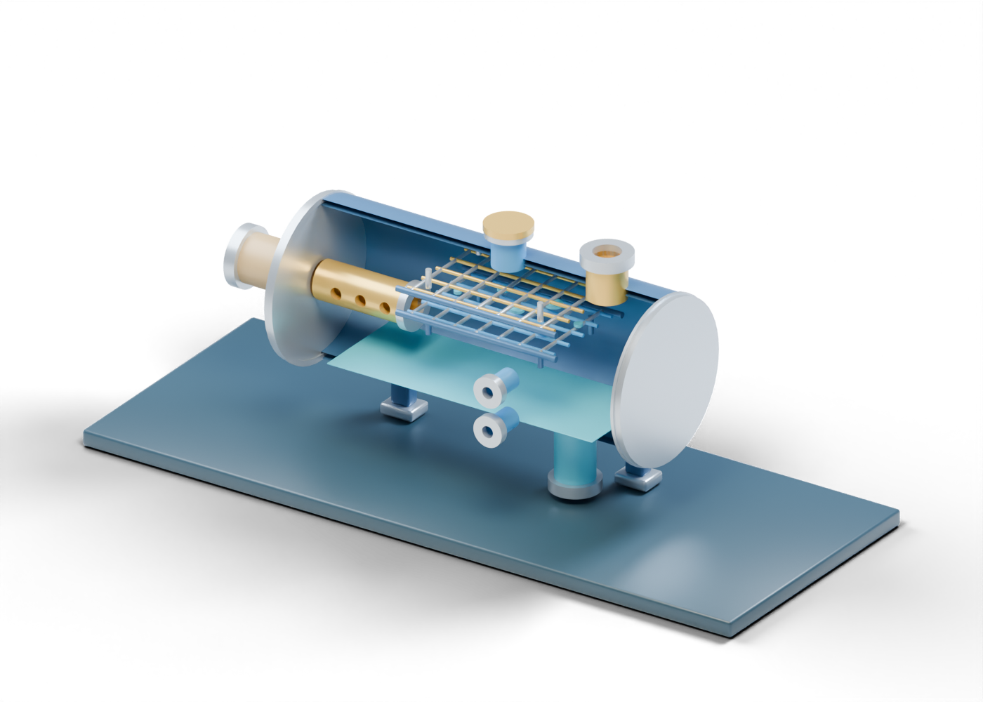
1. What is an electrostatic treater for?
Produced oil may carry water as an emulsion rather than as an easily settled separate layer. US EPA field-processing guidance describes heat treatment and electric treatment as two approaches to this oil-water problem. An electrostatic treater makes water-droplet coalescence a possible step before gravity separation. Its purpose here is upstream oil dehydration. A refinery desalter asks a different question: wash water is deliberately mixed with crude so salts can leave with the water.
The 75-part AlbertaOil 3D lesson lets you inspect a complete enclosure, open feed and output boundaries, and a static grid-region illustration. It represents no selected treater or field installation.
2. Follow the emulsion into the vessel
The open emulsion feed meets the bored end closure. Inside, the hollow entry tube has three real transverse openings and an open axial end. These openings make the arrival path visible; their invented number and location do not establish even distribution or a flow rate. The end ring is a visual boundary, not a selected connection.
The complete vessel wall has distinct openings for the oil outlet, water draw, covered electrical location, side access and two observation locations. The inspection cover closes its opening in the 3D assembly.
3. Read the grid region without inventing an electric field
Two separate open decks, including a lower rail and an upper cross rail, locate a possible coalescence region. The rods are unelectrified in this lesson. They show neither voltage, electrode polarity, spacing selected for a crude, nor field strength. The upper stand-off and lower stand-off mark placement only.
Six fixed blue cues, including reading marker 4, help a reader look for the dispersed-water question. They do not move, collide or settle in the scene. Actual coalescence and dehydration depend on a qualified design and the properties of the emulsion.
| Illustrated element | Helps locate | Does not establish |
|---|---|---|
| Open feed tube | Arrival region | Balanced distribution or selected inlet |
| Two rod decks | Conceptual electrical-treatment region | Energized grid or field strength |
| Fixed blue marks | Dispersed-water reading cue | Droplet paths or removal efficiency |
| Covered entry | Possible electrical-entry location | Power system or safe electrical access |
| Separate outlets | Further oil and water handling | Product quality or approved discharge |
4. Keep the electrical boundary covered
The electrical-entry location reaches a real opening in the vessel wall. An annular seat and solid outer cover keep that location visibly closed. There is no cable, transformer, exposed conductor, insulation design or energization state in the model. The cutaway is a reading view, not a method for working on electrical or pressure equipment.
The upper observation opening and lower observation opening mark separate possible measurement locations, without instruments or a control scheme. VEGA explains why interface position matters near electrostatic grids in a refinery desalter. That source supplies context, not an interface setpoint or electrical design for this upstream illustration.
5. Separate the oil and water destinations
The upper oil boundary and lower water boundary end openly beyond the vessel. The blue water-region plane is an arbitrary visual cue, not a measured inventory or controlled level. Further oil handling and produced-water treatment are outside this scene.
Compare the heater-treater cutaway for a heat-region role, the free-water knockout for bulk gravity separation, and the refinery desalter for an independent wash-water branch. These are separate teaching models, not equipment selected for one process train.
6. Explore the interactive parts
Open the complete AlbertaOil treater lesson and select the feed, open entry tube, first grid region, second grid region, covered entry, oil boundary, and water boundary. The half-section reveals internal locations while the full 3D model retains its complete shell and covers. Neither view is a fabrication drawing, electrical design or operating procedure.