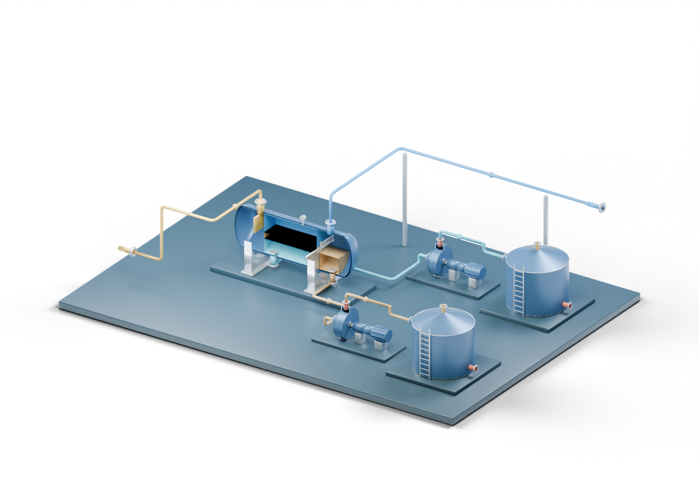
1. Read the layout as a question map
A production facility can put separation, liquid transfer and storage near one another, but their positions in an illustration do not identify a built plant. SLB's three-phase-separator definition distinguishes gas, oil and water outlets. Our original 424-part facility model connects a separate vessel, two pumps and two tanks at invented scales. Its six colored routes are reading aids, not process piping or a flow simulation.
2. Begin at the vessel, then split the questions
The incoming teaching route meets the three-phase separator shell. Inside the vessel, separate oil, water and gas regions make the intended distinction visible. Those colored regions are static illustrations; they do not show interface control, residence time, fluid composition or separation performance.
Follow the oil outlet and water outlet individually. An outlet's presence establishes a conceptual destination, not product quality or a verified discharge. Compare the detailed standalone separator when you want to inspect internals without the surrounding layout.
3. Follow each liquid branch to its limit
The oil route to transfer reaches an oil-pump casing; a second route reaches the oil-tank wall. In parallel, the water route to transfer reaches a distinct water-pump casing and water-tank wall. The pumps are repeated instances of one generic component model. Their presence does not establish selected duty, pressures, fluid compatibility or a safe transfer arrangement.
The water tank is a reading endpoint, not evidence that water is treated or may be released. The oil tank is not an export specification. The standalone centrifugal pump and fixed-roof tank let you inspect parts separately before returning to the scene.
4. Notice where the gas line stops
The gas route leaves the vessel and ends at a separate open handling boundary. No compressor, treatment unit, meter, flare, product-quality result or sales connection follows in this model. A story that says a facility delivers sales gas needs evidence for those additional steps. For a different, independently invented equipment relationship, compare our gas-compression scene; it is not the missing continuation of this battery.
5. Match a real facility claim to evidence
For an Alberta article, identify the actual facility and reporting period before interpreting a production or capacity number. AER Directive 017 sets measurement and reporting requirements for oil and gas operations; a colored model route is no measurement point. AER Directive 055 addresses upstream storage requirements. Its current page and the applicable installation details matter more than the tank shape in this scene.
| Model cue | What it helps you ask | Evidence the model cannot supply |
|---|---|---|
| Three vessel regions | Which actual streams and outlets are reported? | Measured phase split or product quality |
| Two transfer pumps | What duty and service does each real pump have? | Pressure, flow, suitability or operating state |
| Two storage endpoints | Where do actual liquids go after separation? | Containment, venting, capacity or disposition approval |
| Open gas boundary | What gas handling follows the separator? | Compression, treatment, measurement or sales specification |
| Six colored routes | Which source documents define actual connections? | A surveyed layout, P&ID or mass balance |
6. Use the scene alongside the news
Start with the six-stop visual facility study to compare the three branches, inspect 22 exact parts and test the evidence questions. Then open the complete facility explorer, trace one color at a time and select the named parts above. The original Alberta-blue and prairie-gold render gives you a fast overview; the interactive assembly exposes each independently named group. Return to an article with the facility identifier, source document and date in hand. This learning map can organize questions, but cannot validate a claimed production result, equipment selection, environmental compliance or operating procedure.