1. Recognize the equipment role
A fired process heater heats a process stream by transferring heat from combustion through a tube boundary. The American Petroleum Institute overview lists tubes, supports, refractory, stacks, burners and controls among the subjects of API 560 for general refinery heaters. That scope is useful vocabulary; it does not certify this illustration. Our original 94-part heater cutaway is a generic teaching assembly with invented proportions, not a specified Alberta plant or commercial heater.
2. Open the enclosure and identify the lining location
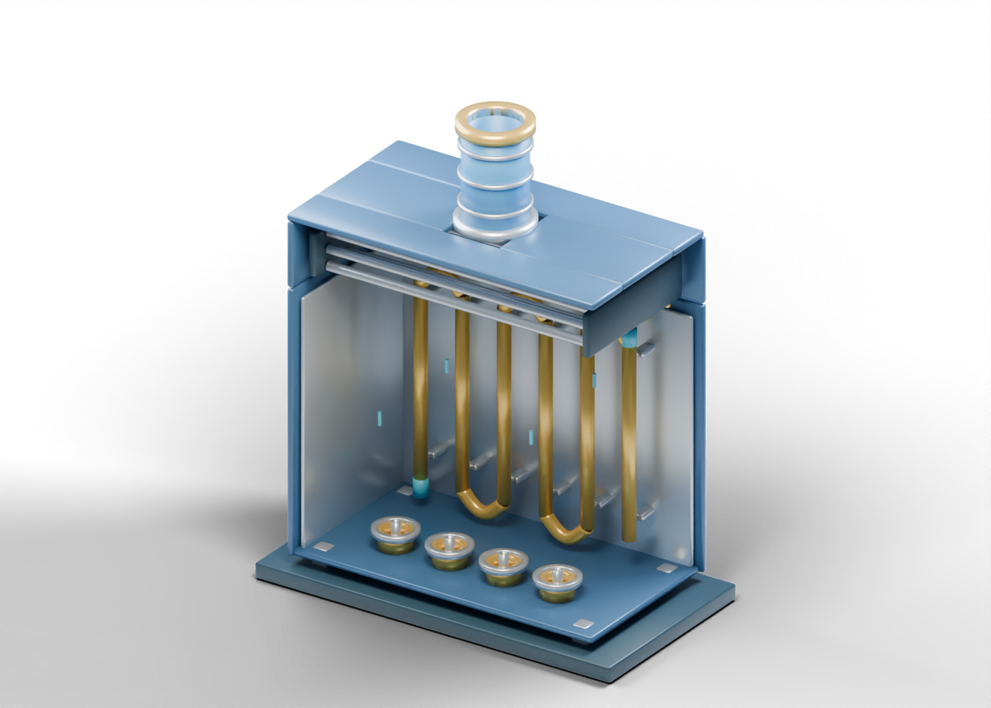
The interactive model retains a complete front radiant-enclosure panel. The still image leaves the facing side out so the interior can be seen. Behind the outer boundary, the rear refractory reading panel marks a distinct lining location. It is a solid shape, not a chosen refractory material, anchorage scheme or verified temperature limit. The upper convection enclosure is similarly complete in the 3D model.
3. Keep burner locations separate from combustion proof
Four open burner throats sit below the radiant-tube region. Each has an independent air-register envelope, fuel-lance envelope and tile-position ring. These are component-location examples. There is no connected fuel train, flame, purge, ignition or burner-management sequence in the model. A visible throat cannot demonstrate stable combustion or a safe operating state.
4. Compare radiant tubes with separate bends
The firebox contains six hollow vertical radiant process-tube examples. Five independent return-bend shapes sit near adjacent ends. Their shape helps explain why a heater story might name tubes and bends separately. Visible proximity is not evidence of a weld, continuous pressure-qualified circuit, flow rate or process outlet temperature. Tube material, thickness, loading and service conditions require real equipment records.
5. Look upward through the convection region
The twelve upper convection-tube examples are separate open tubes rather than a designed connected pass. Four roof-frame pieces leave a genuine central passage beneath the hollow stack. Zeeco's fired-equipment overview describes radiant and convection heat-transfer regions and flue-gas discharge in broad terms. This static picture does not calculate a gas path, draft, heat recovery, stack dispersion or emissions.
| Visible region | Useful reading question | Not established by the model |
|---|---|---|
| Enclosure and lining | Which boundary is being discussed? | Refractory life or structural adequacy |
| Burner locations | Where do fuel and air concepts appear? | Ignition, flame stability or protective functions |
| Radiant tubes and bends | Which parts face the firebox? | Heat flux, tube temperature or process containment |
| Convection bank | Which upper tubes are separate? | Connected pass or duty |
| Open stack | Where does the illustration end? | Draft, emissions or permitted discharge |
6. Check a real heater claim against its evidence
If a project announces a heater replacement, efficiency change or emissions result, identify the actual facility and selected equipment first. Then find the period, measured basis, comparison and relevant permits or engineering documents. A proposed improvement, a product rating and an observed result are different claims. The open upper stack lip merely marks the end of this illustration.
Open the interactive AlbertaOil cutaway to select these parts. Compare its process-heating role with the independent steam-generator concept and heater-treater vessel; they are not interchangeable or one matched plant. These original drawings offer equipment vocabulary and questions for reading the news, without equipment selection, operating or maintenance instructions.