1. Place the vessel in the gas-treatment story
A gas filter separator is a vessel used to remove some solids and liquid from a gas stream before further processing. Parker/PECO training describes a cartridge stage followed by a mist-elimination stage. SLB's gas-treatment overview places removal of solids and liquids among the preparations gas may need. The exact duty depends on the gas and the project.
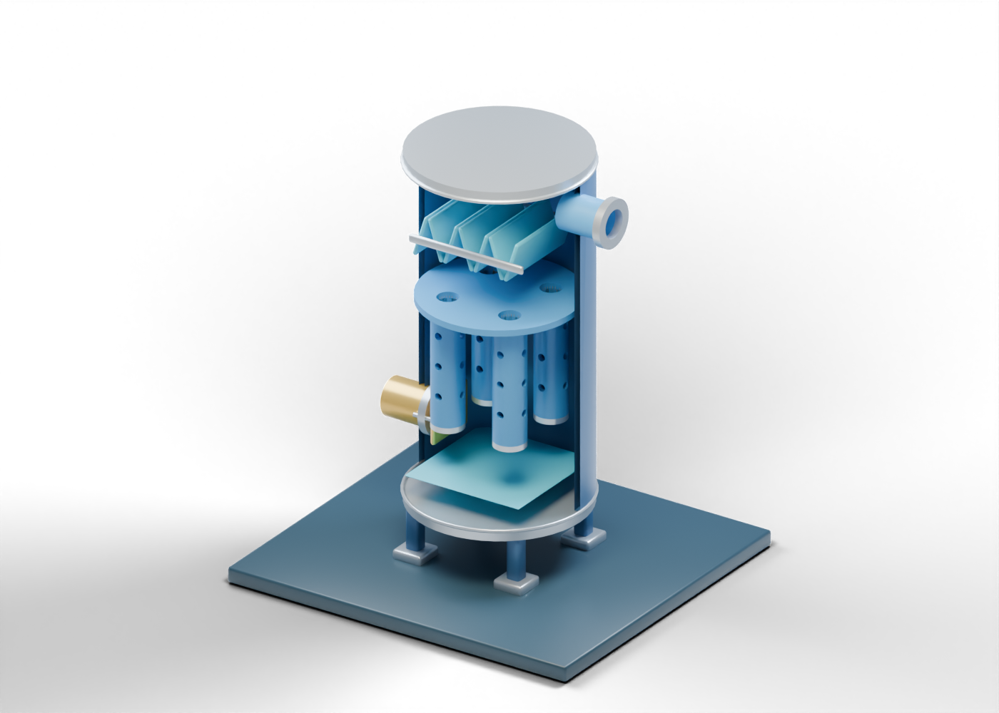
Our original vertical 3D lesson uses an invented arrangement to make those two stages visible. It is neither a named Alberta facility nor a model of a vendor product. The blue and gold poster shows a section; the interactive model retains the complete enclosure.
2. Begin at the inlet boundary
The mixed-gas inlet meets an actual opening in the vessel wall. A separate inlet-diversion marker suggests a place where incoming flow may change direction before the cartridge region. Neither shape gives an inlet velocity, a bulk-liquid removal result or a safe operating limit.
The complete double-surface wall has an inner and outer face. The inspection location has a closed cover in the browser model. The model cannot be used as a vessel-entry or maintenance procedure.
3. Inspect the first stage
Four individually selectable cartridge envelopes have open centres and visible radial holes. Their aligned collector plate has four actual bores. These are original geometric cues for a first-stage role, not specified filter media. Parker's broader natural-gas filtration overview describes filtration equipment in context; it does not validate this drawing or select elements for an Alberta gas stream.
A real application would need gas composition, particle and liquid loading, target removal, element specifications and pressure-drop analysis. Hole count and colour in a teaching model do not supply those facts.
| 3D element | Helps locate | Does not prove |
|---|---|---|
| Open inlet neck | Arrival boundary | Feed composition or rated connection |
| Four cartridge envelopes | First-stage location | Filter grade, life or solids capture |
| Four-hole collector plate | Separate cartridge passages | Even distribution or leak-tight seals |
| Seven upper slats | Second-stage mist-removal location | Droplet capture or pressure drop |
| Lower drain and blue plane | Separate liquid destination | Actual level, valve logic or disposal permission |
4. Compare the second stage and outlets
Seven separate upper mist-vane markers represent a different treatment location above the cartridges. Their profile and spacing are invented. The gas outlet marks a destination, but the geometry says nothing about gas dryness or downstream specifications.
The lower liquid drain passes through a real bored cap. The blue sump plane is a fixed label at an arbitrary height. It does not show a measured interface, liquid inventory or control response.
5. Compare neighbouring equipment without treating it as one designed train
A slug catcher illustrates temporary inlet liquid handling. A gas-liquid coalescer illustrates a separate droplet-removal concept. A dry cyclone separator illustrates another solids-separation concept. The four lessons explain different roles; their drawings are not compatible specifications or a connected plant.
When a project story claims cleaner gas or increased capacity, ask which inlet and outlet were sampled, what contaminants were measured, the time period, pressure drop, element condition and downstream requirement. No render can verify those claims.
6. Explore exact parts
Open the vertical filter separator in AlbertaOil's existing atlas, reveal its interior, select one cartridge, compare the mist marker and trace the gas outlet and liquid drain. The 49 named components and verified bores make the teaching geometry inspectable. They do not qualify filtration, separation, pressure integrity or operation.