1. Find the connection between driver and driven machine
A coupling joins a driver-side shaft with a driven-machine shaft. It has a different role from a bearing that supports a shaft or a seal region that limits passage around one. Rexnord's undated pump-packager page places disc-coupling products in pump, blower and air-compressor spacer applications. That supplies application vocabulary, rather than evidence for our geometry or a particular Alberta installation. Rexnord: spacer-coupling application context.
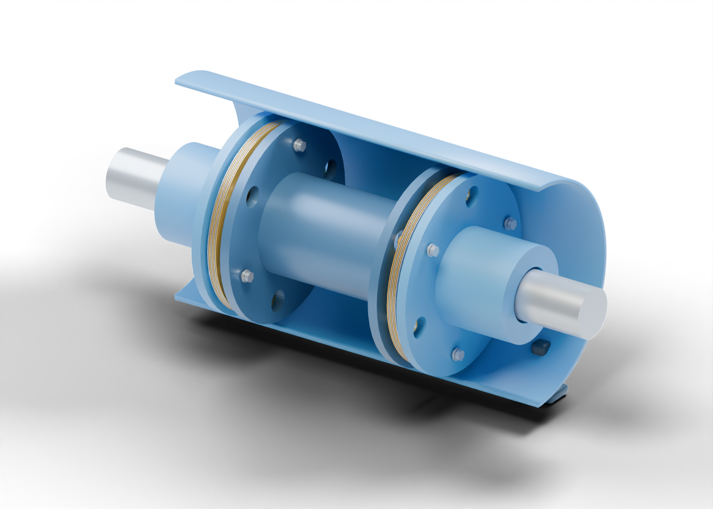
Our original static assembly has 105 named mesh instances and twelve exact-part studies. Two blue bored hubs surround separate silver shaft segments. Two laminated packs sit on opposite ends of a hollow centre spacer. Separate flanges, sleeve and hardware regions distinguish the attachment locations. A two-piece guard-shaped enclosure is independent of the coupling.
There is no matched pump, driver or compressor attached to these shaft envelopes. Their proportions are invented, and no selected duty or compatibility is established.
2. Read twelve laminae as layers in two packs
Each pack contains six individually selectable thin annular laminae, with six actual geometric openings per lamina. Alternating gold and silver layers make the stack easier to read. Across both packs, twelve layers contain seventy-two openings. These are repeated members of one original assembly, rather than twelve different coupling designs.
Deliberate spaces expose the layers for inspection. A flat, separated teaching stack does not establish a clamped operating pack, a specified sheet material, bending stiffness or fatigue life. The model supplies no flexure, angular misalignment or axial displacement calculation. Orbiting the view moves the camera; the component geometry remains static.
3. Follow alternating attachment locations
At each pack, three hub-side and three spacer-side attachment locations alternate around the flanges. A smaller geometric opening identifies an assigned attachment region; the opposing flange has a larger bypass opening. Hollow sleeves, smooth bolt markers, separate head and washer shapes, and bored hexagonal nut envelopes distinguish these regions.
The centre spacer is a separate hollow tube between two spacer flanges. The independent shaft segments stop outside its centre region. This helps readers distinguish a shaft envelope, a hub and the central member without treating them as one solid part.
The illustration has distinct openings and fastener locations but does not establish fit, clamp load or fatigue life. The visible parts do not establish fitted contact, preload, force distribution, torque transfer or a complete collision analysis. No thread, keyway, clamp, interference fit, weld detail or tightening value is provided.
4. Separate a visible feature from an engineering result
| Original region | What can be inspected | What needs separate evidence |
|---|---|---|
| Two shaft segments and bored hubs | Separate shaft envelopes, real hub openings and deliberate gaps | Shaft engagement, key/clamp/fit selection and duty compatibility |
| Twelve laminae | Thin flat layers, seventy-two true openings and separated pack locations | Specified pack construction, flexure, stress, fatigue and misalignment capacity |
| Alternating flange locations | Three smaller attachment and three larger bypass openings per flange | Qualified contact, fit, load distribution and torque transfer |
| Sleeves and joint hardware | Hollow sleeves, separate washers, smooth bolt/head and bored-nut regions | Threads, engagement, preload and tightening specification |
| Hollow centre spacer | A separate central member between the two pack regions | Selected span, weld construction, balance and speed/torque rating |
| Guard halves, end markers and feet | Separate enclosure-shaped parts, shaft openings and four foot bores | Guarding/access protection, attachment strength, anchors and foundations |
The still hides the facing guard half, end markers and guard supports to show internal parts; the interactive model retains them. The full interactive model retains them. These presentation choices expose the assembly without prescribing guard removal, installation or a service sequence.
5. Ask what a reliability headline actually measured
A coupling-replacement or alignment headline can refer to a specific machine, chosen product, installation work or a measured operating result. Identify the asset, intervention, record dates, comparison period and measurement source. A photograph or a drawing alone does not supply those records.
For this teaching assembly, two pack locations are visible. No rated deflection, speed, torque, fatigue life, balance grade or alignment acceptance result is supplied. Its enclosure-shaped parts are not a certified guard, and the geometry is not an inspection finding or a claim that a real machine can run safely.
Read a manufacturer or operator claim in its stated context and link the underlying evidence. This guide supplies equipment vocabulary and an original illustration; it reports no plant performance, diagnoses no fault and recommends no replacement part or maintenance action.
6. Inspect exact components and compare their roles
Open the spacer disc coupling for the whole assembly. Inspect the first driver-side lamina, the first spacer-side attachment sleeve and the hollow centre spacer as exact named components.
Compare the housed roller-bearing lesson and mechanical face-seal lesson. They distinguish support, connection and sealing roles. Their independent invented proportions do not establish a compatible machine, a selected coupling or a replacement installation.